Once I bought my MSI MAG B650M MORTAR motherboard I wanted to get the fastest possible CPU which is the AM5 AMD Ryzen 9 7950X CPU. This CPU was the best decision and worked better than I was expecting. I found this CPU on Amazon and it was $531.91. This price could change depending on the market and sales. At first, I was skeptical because of the price but after installing it I knew I made the right decision. I bought this CPU to be fast and be able to run any game and it is capable of that. 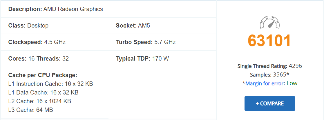 When first researching this CPU the most impressive part of the product was the passmark rating. This CPU’s passmark rating was in incredible 63101. Please note that this passmark rating can change if someone uploads a new rating. This rating as well as all my other information was found on the passmark CPU website where you can compare it to other CPU’s. I decided to run farming simulator 19 and it ran better than any other CPU I’ve ever had. It didn’t lag at all even with all of the mods I use that usually slows my game.
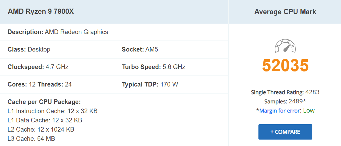
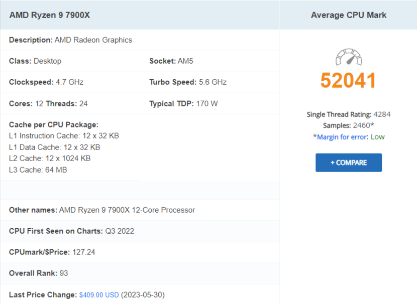
This CPU has an amazing clock speed of 4.5 GHz as well as having 16 cores and 32 threads. It also has and L1 instruction and data of 16 x 32 KB. It has a L2 rate of 16 x 1024 as well as a L3 rate of 64 MB. This all together makes its amazing cache which runs my computer beautifully.
Note: This review is part of a classroom project.
Works Cited:
“AMD Ryzen™ 9 7950X 16-Core, 32-Thread Unlocked Desktop Processor.” Amazon.com, https://www.amazon.com/dp/B0BBHD5D8Y?tag=cpubenchmark-20&linkCode=osi&th=1&psc=1. Accessed 23 January 2024.
“PassMark – AMD Ryzen 9 7950X – Price performance comparison.” CPU Benchmarks, https://www.cpubenchmark.net/cpu.php?cpu=AMD+Ryzen+9+7950X&id=5031. Accessed 23 January 2024.