- Assumptions
- You need to resize a drive without a GUI.
- You have made some backup of your VM/Physical drive
- Notes
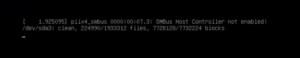
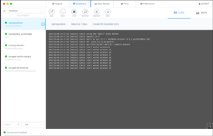
- I got locked out of my Ubuntu Desktop GUI for this tutorial and have to putty to the machine as shown in the image below.
- List you disks
- df -h
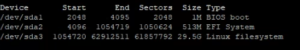
- You will get a large output but you need to look for something similar to this
- df -h
- Find the partition that is out of space. (mine was /dev/sda3/)
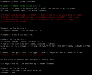
- sudo fdisk /dev/sda
- Delete and remake the partition (YOU WILL NOT LOSE DATA), mine was partition 3
- d
- delete a partition
- 3
- Partition 3
- n
- Make a new partition
- 3
- Make it partition 3
- PRESS ENTER TWICE
- Specifying the starting and ending blocks. I want the default so I press enter for both questions.
- Y
- Yes, delete the signature
- w
- Write the changes.
- Control + C
- Exit fdisk
- d
- Resize the file system
- sudo resize2fs /dev/sda3
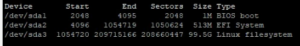
- Verify the changes were made
- df -h
- The new size of your file system will be shown.
- df -h
All posts by Maverick Peck
Docker Management
- Assumptions
- You have installed and configured docker using the documentation here.
- Install Docker Desktop
- Docker Desktop is a Windows solution to having the docker engine on Windows 10/11 (THIS CAN NOT RUN ON WINDOWS SERVERS) and can be downloaded here.
- After running the install, there will be a checkbox asking if you want to run it using WSL2, uncheck this as most Windows systems don’t have this downloaded by default and HyperV works just as well.
- After installing and restarting, move on
- Install DockStation
- This is a GUI for creating, managing, and deleting Docker containers on both remote and local Docker Hosts.
- To install this, go the the web address here and download the Windows executable. Just run the .exe file and click next until the app is installed.
- This is a GUI for creating, managing, and deleting Docker containers on both remote and local Docker Hosts.
- DockStation Configuration
- Now that you have DockStation installed, you need to connect it to your remote server.
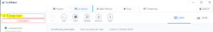
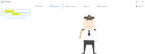
- To do this go to the “Containers” top and go to the top left and edit the machine it is connected to (changing it from localhost).
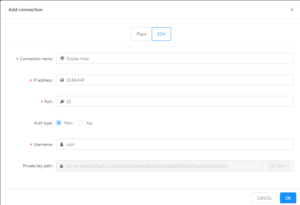
- You will then add a new connection and log in via “SSH”. You will enter the IP address of your docker host and enter a username that has access to the docker application on that host (I am going to use root).
- You then need to make sure you have the correct connection selected and click “connect” to connect to the Docker instance.
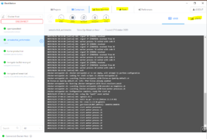
- Once you log in, you will be able to view your docker machines, create new ones, connect to the shell of these machines, delete them, monitor them, and so on.
Swapping HDD On LSI MegaRAID 9361-8i
- Assumptions
- You have powered down the machine (safely of course)
- The server is unplugged and residual power has been drained.
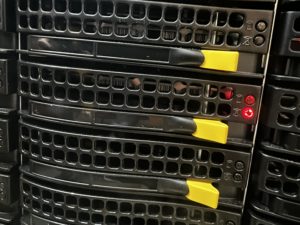
- Find the broken drive
- This is indicated via the red LED on the front of the drive bays.
- FLASHING RED = HOT SPARE
- SOLID RED = BROKEN/BAD HDD
- Remove the drive from the drive bay and replace it with a drive of the EXACT same model. If it is a different model, it can not be added as a hot spare, only as an “Up Good” drive.
- This is indicated via the red LED on the front of the drive bays.
- Power on the Server
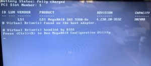
- As the server powers on, it will conduct tests such as normal POST and gather information on the RAID controller. As the machine powers on, you will eventually come to the following screen after some minutes of booting.
- Once this screen comes up, press “CTRL + R” to enter the raid controller settings. The screen will look like the following.
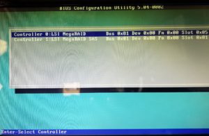
- Once you get to this screen, press enter to enter the primary RAID controller settings.
- As the server powers on, it will conduct tests such as normal POST and gather information on the RAID controller. As the machine powers on, you will eventually come to the following screen after some minutes of booting.
- Configure the drive and add it as a Hot Spare
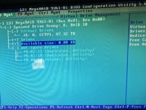
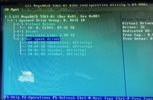
- Once you are in the RAID controller, it will look somewhat like the following.
- As you can see, there are only THREE hot swap drives. We need to add the new drive to act as the fourth spare.
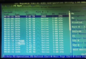
- To do this, tab over to “PD Mgmt” to see all of the disks. The screen will look as follows.
- Here you can see a list of all drives connected to the RAID controller. The one in the”JBOD” state is going to be the drive that needs to be changed.
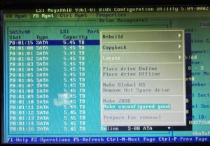
- To do this, press “F2” while hovering the drive to bring up the options. You will then be presented with the following menu.
- In this menu, you will select “Make Unconfigured Good” to change the drive to an “Up Good” state. You will then go back to the menu to make it a Hot Spare.
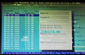
- Once you are back to this menu, select “Make Global HS” to make it a Hot Spare for all virtual drives.
- You can then go back to “VD Mgmt” and expand the “Hot Spare Drives” section to see your new hot spare!
- Once you are in the RAID controller, it will look somewhat like the following.
- Reboot the Server
- You can now reboot the machine and bring it back to full operation!
Docker Install and Configuration
- Assumptions
- You have an Ubuntu 22.04 Linux server created
- 4GB of RAM
- 30GB of Drive Storage
- You have an Ubuntu 22.04 Linux server created
- Install Docker
- sudo apt-get update
- sudo apt-get install ca-certificates curl gnupg
- sudo install -m 0755 -d /etc/apt/keyrings
-
curl -fsSL https://download.docker.com/linux/ubuntu/gpg | sudo gpg --dearmor -o /etc/apt/keyrings/docker.gpg - sudo chmod a+r /etc/apt/keyrings/docker.gpg
-
echo \ "deb [arch=$(dpkg --print-architecture) signed-by=/etc/apt/keyrings/docker.gpg] https://download.docker.com/linux/ubuntu \ $(. /etc/os-release && echo "$VERSION_CODENAME") stable" | \ sudo tee /etc/apt/sources.list.d/docker.list > /dev/null - sudo apt-get update
- sudo apt-get install docker-ce docker-ce-cli containerd.io docker-buildx-plugin docker-compose-plugin
- Add Current User to Docker Group
- By default, only the root user can do docker commands, you need to add your current user to the docker group in order to allow it to run docker commands.
- sudo groupadd docker
- sudo gpasswd -a $USER docker
- newgrp docker
- By default, only the root user can do docker commands, you need to add your current user to the docker group in order to allow it to run docker commands.
- Test Docker installation
- docker run hello-world
- This command runs a test docker container to see if your installation functions normally. The output should look like the image below
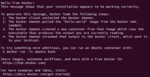
- docker run hello-world
Configuring Nginx for HTTPS Redirect
- NOTES
- If you already have nginx deployed, skip to the “Add a website for URL redirect” step.
- Assumptions
- You have an Ubuntu 22.04 Linux server created
- 4GB of RAM
- 30GB of Drive Storage
- You have an Ubuntu 22.04 Linux server created
- Prerequisites
- You have a DNS “A” record redirecting all subdomains to your machine.
- For instance, if your domain is “example.com”, you need to create an A record of “*” to redirect everything to anysubdomain.example.com.
- You have a DNS “A” record redirecting all subdomains to your machine.
- Download openssh (OPTIONAL)
- This allows the user to ssh into the machine to allow for easier copying and pasting of commands
- sudo -i
- This puts the current terminal as a super user (can run commands as an admin).
- apt-get update
- Updates the current list of Linux packages.
- apt-get upgrade
- Upgrades all of the packages/updates the actual software
- apt-get install openssh-server
- This installs openssh so you can ssh to the Linux machine
- sudo -i
- Connect to the Linux machine via SSH (use putty or the cmd)
- This allows the user to ssh into the machine to allow for easier copying and pasting of commands
- Install nginx
- apt install nginx
- This installs the nginx software and engine
- systemctl status nginx
- this will check the status of nginx, ensuring the it is running
- apt install nginx
- Add a website for URL redirect
- cd /etc/nginx/sites-available
- nano yourwebsite.example.com
- You will want this to actually be the URL you are redirecting. For instance, test.nationaltrail.us. “test” is the subdomain and “nationaltrail.us” is the domain we own.
- Add the following configuration to the file
- server {
server_name test.nationaltrail.us;location / {
proxy_pass http://10.10.8.112; # Point to test web server
proxy_set_header Host $host;
proxy_set_header X-Real-IP $remote_addr;
proxy_set_header X-Forwarded-For $proxy_add_x_forwarded_for;
}
}- This redirects “test.nationaltrail.us” to “http://10.10.8.112”
- server {
- Link sites-available to sites-enabled
- ln -s /etc/nginx/sites-available/test.nationaltrail.us /etc/nginx/sites-enabled
- This creates a link from sites-available to sites-enabled to allow nginx to start redirecting/have access to the configuration
- ln -s /etc/nginx/sites-available/test.nationaltrail.us /etc/nginx/sites-enabled
- Test the configuration
- nginx -t
- This should have an output such as “the configuration is OK”
- nginx -t
- Restart the nginx service
- systemctl reload nginx
- You should now ab able to go to “test.nationaltrail.us” to go to the website located at “10.10.8.112”
- Add Certbot and secure the site
- At this point, you are only redirecting traffic, not adding an SSL certificate. This will add encryption to secure the site.
- Install certbot and the nginx plugin
- apt install certbot python3-certbot-nginx
- Secure your website
- certbot –nginx -d test.nationaltrail.us
- Go through the installation process. This includes adding a notification email for certificate expiration AND choosing the option for REDIRECTING traffic to HTTPS. This is the second option if you are prompted for it.
- Restart nginx
- systemctl reload nginx
- Connect to your website! It should be secured unless the web app requires further proxy configuration (refer to the webpages documentation for this possibility).
Connecting to a Docker Container Using Ubuntu Terminal
- NOTE: You can do other commands such as copy files from the container to your VM, install tools in the container, and anything that can be done on a regular Ubuntu install. For more information, look in the DOCKER DOCUMENTATION.
- Assumptions
- You are using Ubuntu/Debian-based OS
- You have Docker installed
- You have a running container
- You have access to the docker environment
- Get the docker ID and list the containers
- Open Ubuntu Terminal
- docker ps
- This allows you to get a list of all docker containers
- docker ps
- The docker ID is the first string of numbers and letters before your container
- Enter the docker container
- docker exec -it <your container ID> bash
- docker exec -it 175cb158268e bash
- docker exec -it <your container ID> bash
- Open Ubuntu Terminal
- You can now execute commands in the container just as you could in a regular Ubuntu Server.
Creating a Azure DevOps/Kubernetes On-Premise Platform
- Assumptions
- You already have a vCenter virtual environment with permission to create virtual machines.
- This environment is fully licensed.
- You have prior knowledge of how to create a virtual machine (Can make a Windows Server 2022 machine).
- You already have a vCenter virtual environment with permission to create virtual machines.
- Prerequisites
- On Personal Machine
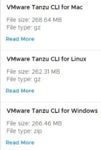
- Download and install the Tanzu Grid CLI tools from the VMWare website
- Download, install, and open Docker Desktop on your machine
- On vCenter
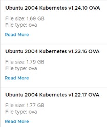
- You need to download the Tanzu base image (OVA file) from the VMware website, upload it to your server and convert it to a template. (When you do the initial setup on the Tanzu you will know what version you need)
- On Personal Machine
- Create an SSH Public key on your vCenter environment
- Generate a public key using Puttygen or other key-generation softwares
- SSH to the vCenter server using Putty or another SSH service
- Enter the following commands and change the following lines
- vi /etc/ssh/sshd_config
- CHANGE: PermitRootLogin no” to “PermitRootLogin yes”
- vi /etc/ssh/keys-root/authorized_keys
- Add the key you created
- /etc/init.d/SSH restart
- vi /etc/ssh/sshd_config
- Do the Tanzu Installation
- Enter the following commands into the command line
- tanzu init
- tanzu mc create -u
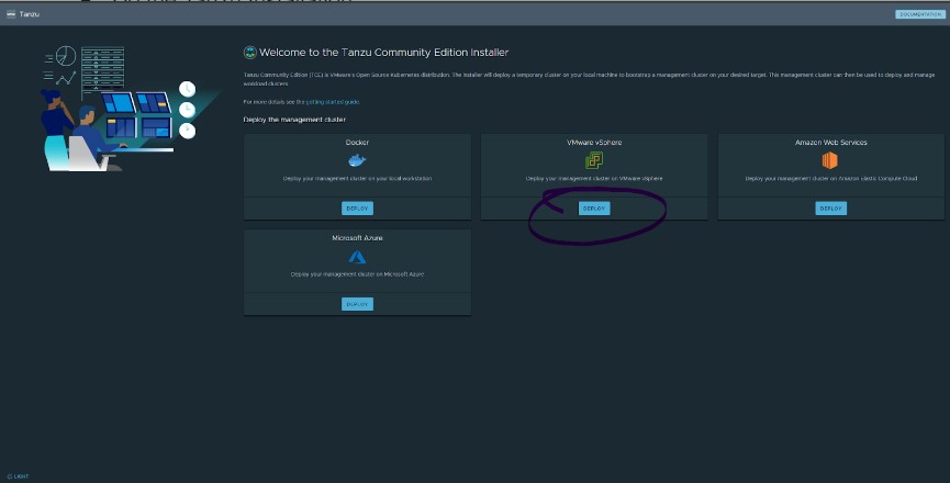
- You will be presented with a web GUI for the Tanzu installation
- Select “Deploy” under the VMware vSphere option
- Under the IaaS Provider Option
- IP or FQDN
- Enter the IP address/DNS name of your virtual environment
- Username
- Enter the username of an administrator account for vCenter
- Password
- The password to the account name you provided
- Disable verification
- Unchecked
- SSL Thumbprint Verification
- Check “Disable Verification”
- Click Connect
- Select the datacenter you have set up in vCenter
- SSH Public Key
- Enter the same public key you put in your vCenter config files
- IP or FQDN
- Under Management Cluster Settings Tab
- Deployment
- Select the desired instance type; I used small
- Management Cluster Name
- Give your new cluster a name
- Control Plane Endpoint Provider
- Kube-vip (for simplicity’s sake)
- Worker Node Instance Type
- I used small
- Control Plane Endpoint
- Give your cluster an unused IP address
- Deployment
- VMware NSX Advanced Load Balancer
- LEAVE THIS BLANK
- Metadata
- LEAVE THIS BLANK
- Resources
- VM Folder
- Select the folder that you want your VMs to be a part of.
- Datastore
- Select the datastore you want your machines to be stored
- VM Folder
- Kubernetes Network
- Network Name
- Select the port group/vCenter network you want to use.
- Cluster Service CIDR
- Leave Default
- CLUSTER SERVICE CIDR
- 100.64.0.0/13
- CLUSTER POD CIDR
- 100.96.0.0/11
- CLUSTER SERVICE CIDR
- Leave Default
- Network Name
- Identity Management
- DISABLE THE CHECKBOX TO BLANK THIS OUT
- OS Image
- Select the template you made earlier in the installation process
- Select “Review Configuration” and finish the installation
- Enter the following commands into the command line
- Deploy an Azure DevOps machine
- Create a Windows Server VM (I used 2022)
- Download the Azure DevOps Server Tools
- This is a very typical setup wizard (basically just clicking next 5 times). It will install Java and SQL for you if you do not have them already.
- After an uneasy amount of time, the installation will be complete (you may need to restart). You can then open the Azure DevOps Server Administration Console.
- You can then connect to the web GUI through a web browser
- http://azure-devops OR http://SERVER _IP_ADDRESS
- You can then connect to the web GUI through a web browser
- The username and password are the same as the Admin user account on the Windows Server 2022 server
- You can add other users in the administration console under the “Application Tire” tab under “Administration Console Users”
- Create a Windows Server VM (I used 2022)
- Connecting Everything Together – The Finale
- In the Azure-DevOps web GUI, go to “Collection Settings” located at the bottom left.
- Go to the “Agent Pools” tab toward the bottom left
- Select the Default Agent pool
- Select “New Agent” at the top right
- Follow the instructions prompted to you on the screen (downloading a zip file, making a few directories, and such).
- I HAVE USED THE SAME 2022 SERVER FOR BOTH HOSTING THE DEVOPS WEBSITE AND THE AGENT TOOLS.
- Run “config.cmd”
- Enter Server URL
- https://AZURE_DEVOPS_IP_ADDRESS
- Press enter for the integrated authentication type
- Run this as a service so it starts when the machine starts
- Enter Server URL
- Run “config.cmd”
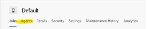
- Go to the “Agents” tab in the Default Agent Pool section
- There should now be an Agent that is currently online
- Connect the Kubernetes cluster to a pipeline
- In the Azure DevOps console, create a new Project on the main screen
- Go to the “pipelines” selection on the left
- Select “Environments”
- Create Environment
- Give it a name
- Select Kubernetes as the Resource
- Provider
- Leave Default
- Cluster Name
- This will be what you named your cluster when you created the Tanzu Cluster
- Namespace
- You can use the “default” namespace for simplicity’s sake
- Server URL
- Secret
- In a command line interface, connect to your Tanzu Cluster
- tanzu init
- tanzu login
- Select your cluster and hit enter
- Create a new service account
- Download the file located HERE
- Change your directory to your downloads folder in the command line
- Execute a command to run the YAML file
- kubectl apply -f azure-devops-service-account.yaml
- Get the token for the service account
- kubectl get serviceAccounts <service-account-name> -n <namespace> -o=jsonpath={.secrets[*].name}
- Use the token to get the secret
- kubectl get secret <service-account-secret-name> -n <namespace> -o json
- Replace the <Service Account Secret Name> with the token you got from the previous command
- kubectl get secret <service-account-secret-name> -n <namespace> -o json
- Enter the output you got from that in the Azure DevOps “Secret” textbox.
- In a command line interface, connect to your Tanzu Cluster
- Check the “Accept untrusted certificates” checkbox
- Finish by clicking “Validate and Create”
- Provider
- In the Azure DevOps console, create a new Project on the main screen
Creating an ISCSI Share On Ubuntu Linux and Connecting it to Windows Server 2022 on Icebreaker 4936 Server
This is a blog post focusing on creating an ISCSI share on Ubuntu Linux on an Icebreaker 4936 Server. This will act as a mass storage ISCSI store for a Windows file and video server. I will describe the process of creating the ISCSI server, connecting it to Windows, and ensuring a stable connection through a series of scripts on Windows.
OS: Ubuntu Linux 22.04
- Assumptions
- You have already completed the “Quick Start Guide” by connecting the raid controller components to each other inside of the case.
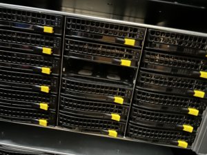
- The hard drives have already been slotted into the hot swap bays.
- The system is able to be powered on and is capable of entering BIOS.
- You have created an Ubuntu Linux bootable USB drive.
- You know how to install Windows 10/Windows Server and Ubuntu 22.04.
- Connect a keyboard, mouse, and monitor to the server.
- Create a bootable disk to Windows 10/Windows Server 2016 or newer to do drive testing.
- Download the Seatools drive testing software.
- Download the StorCLI command line tools.
- Open the command prompt and navigate to the directory where the storclt.exe executable is.
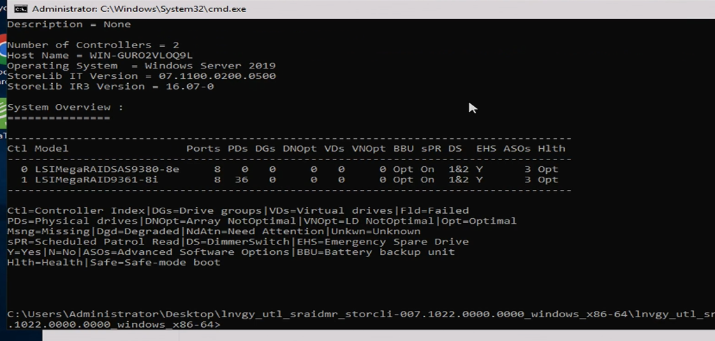
- List all RAID controllers
- storcli show
- There should be a list of two raid controllers, one with no PDs, and one with 36.
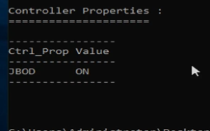
- Put the RAID controller in JBOD mode.
- storcli /c1 set jbod=on
- Put disks in JBOD mode
- storcli /c1/eall/sall set jbod
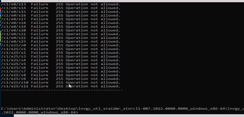
- It WILL say that each disk failed to go to jbod mode. This is not true, the operation worked.
- Restart the server
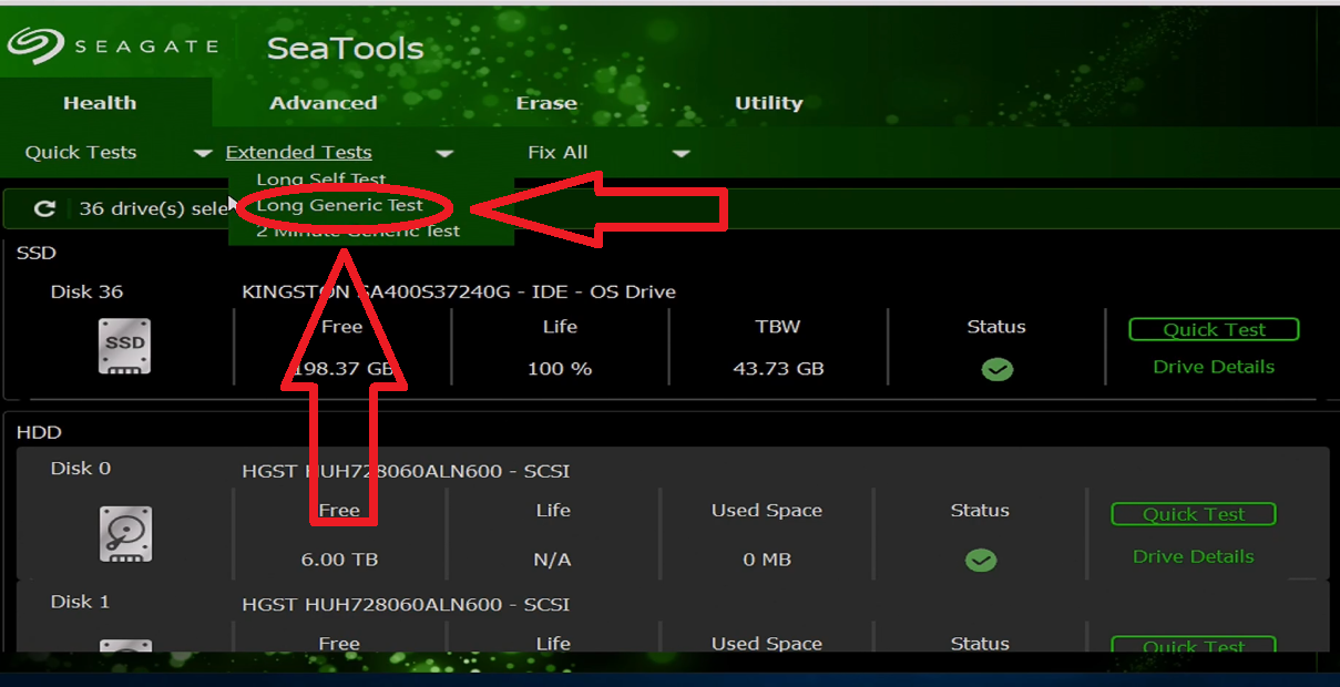
- Open the Seatools software. There should be all 36 drives + the OS drive.
- Select every drive you want to test. This can be done by doing “Ctrl + Left Click” to select multiple drives at once.
- Perform a Long Generic Test by clicking the button as shown in the photo below.
- After multiple days pass, you should be left with an outcome of what drives are good/bad. Replace the bad ones if necessary.
- Restart on the machine to boot to the RAID controller.
- After the initialization screen and the HDD check screen, there will be a brief moment where you can press “ctrl + R” to boot to the RAID controller. This will appear shortly after the following boot screen.
- Once on the controller interface, you can select your RAID configuration. This includes the RAID level, which drives you to want to use, setting up hot failover, and how many physical drives you want for each logical drive. In my case, I used RAID 10 with 18 drive logical drives (18 striped, 18 mirrored).
- The RAID card included with this server supports RAID 0, 1, 5, 6, 10, and 50. For more information and visualizations of the different raid levels, visit the link HERE.
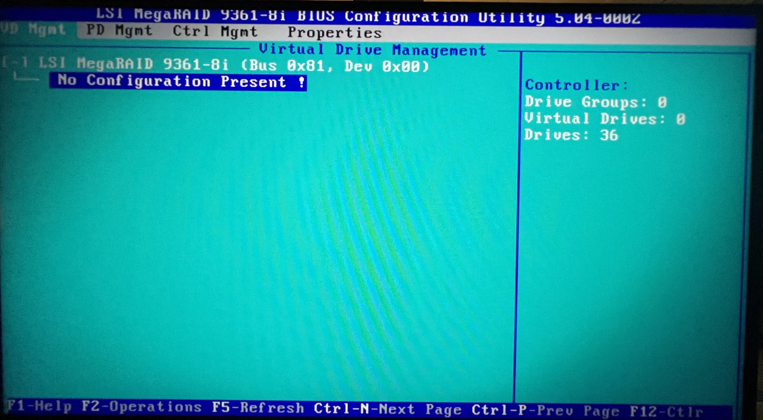
- The main screen of the RAID controller should look like the photo below.
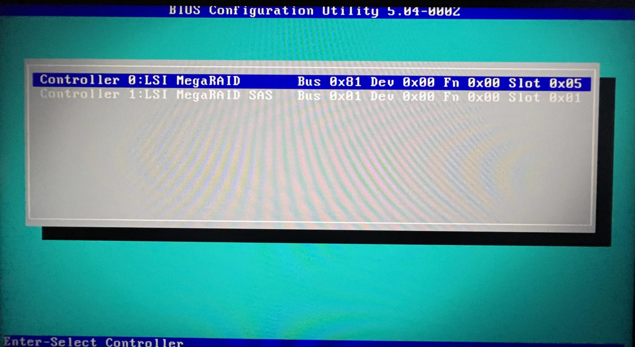
- You then need to select the “Controller 1: LSI MegaRAID SAS” card to configure the drives.
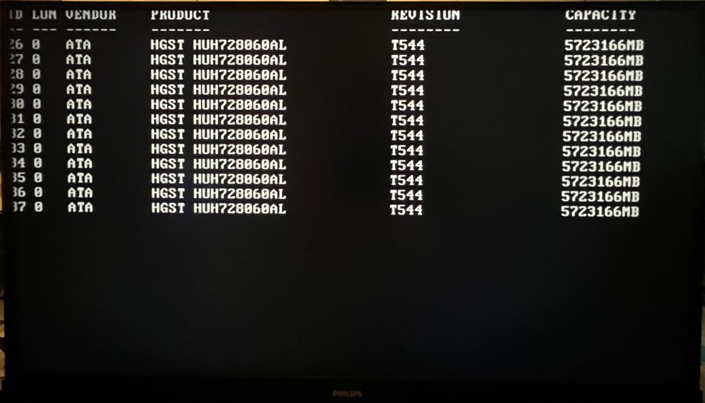
- You will be greeted with a mostly-empty screen that looks like the following.
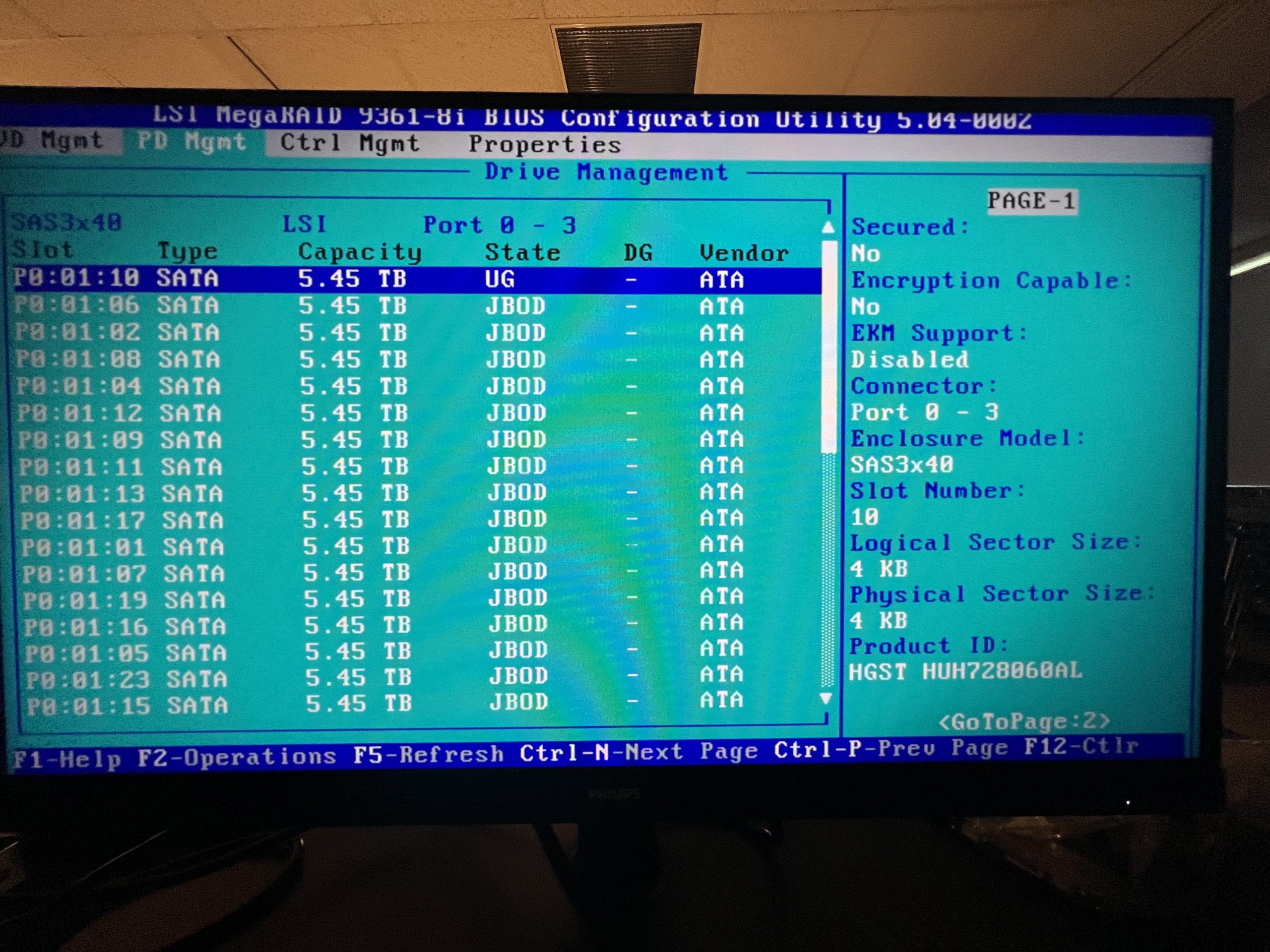
- Press “Crtl + N” to go to the “PD Mgmt” page where you will be a list of disks in “JBOD” mode.
- Select each disk one at a time
- Press “F2”
- Select “Make Unconfigured Good”
- Say “Yes” to the warning about losing data.
- Repeat until all disks are in “UG” mode like the one shown below.
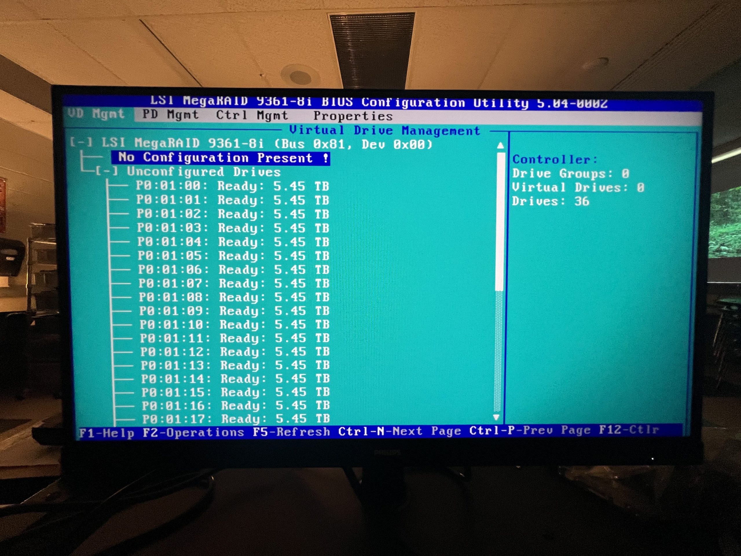
- Press “Ctrl + P” to go back to the “VD Mgmt” page.
- There should be a large list of unconfigured drives that are “Ready”.
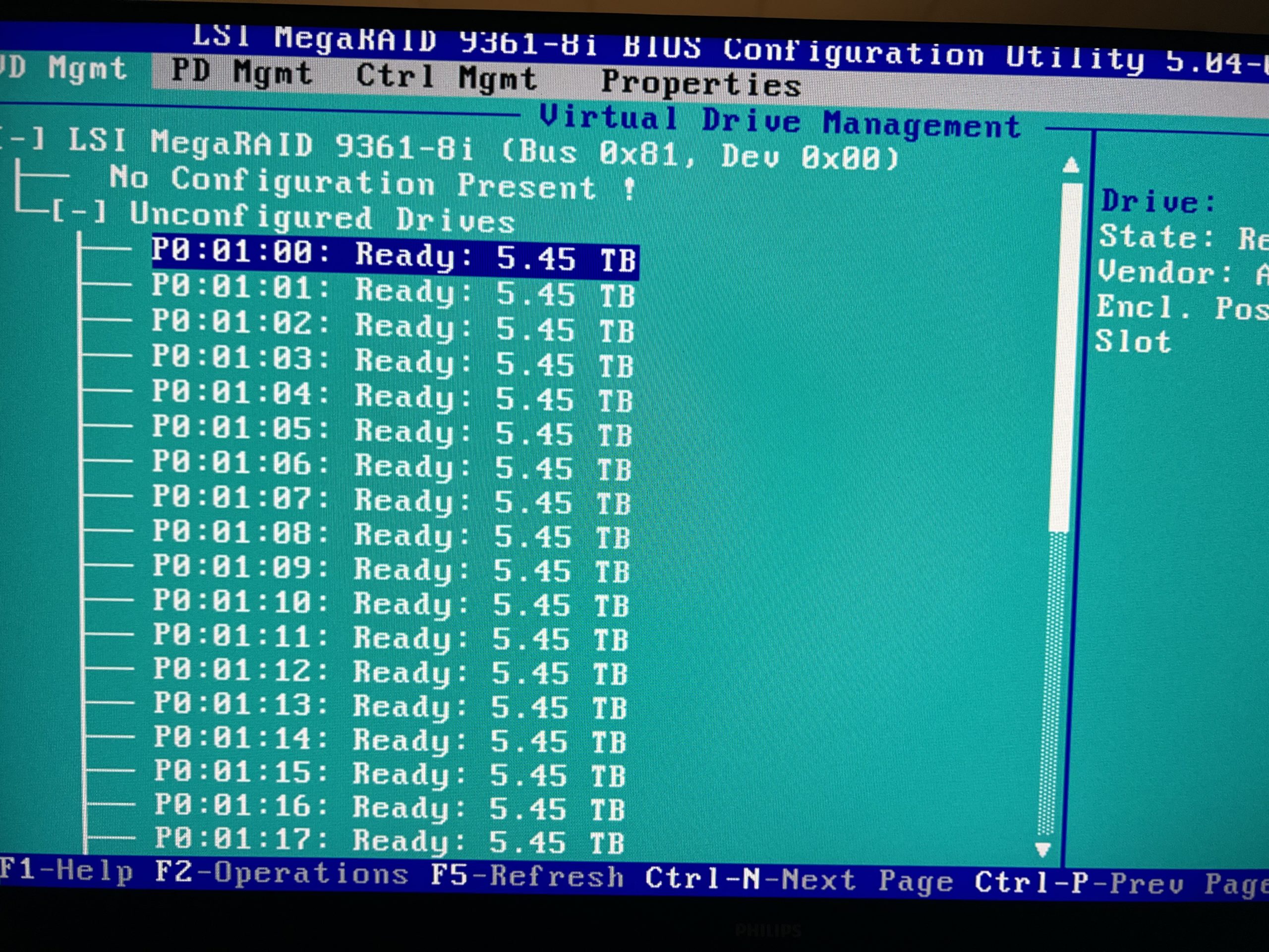
- Scroll up to where it says “No Configuration Present!”
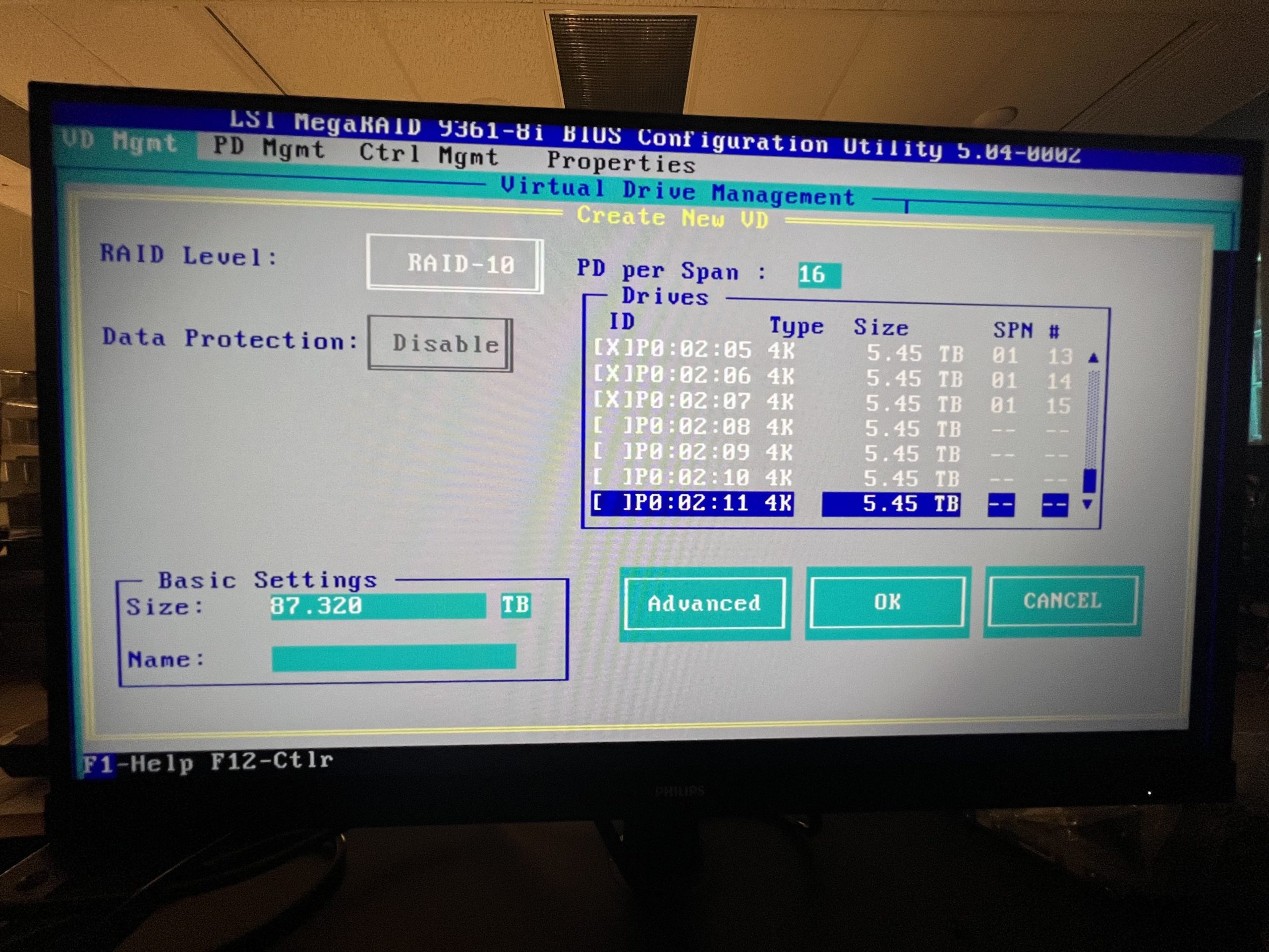
- Next, press “F2” to enter the Raid Setup menu.
- Here, select “Raid-10” for the RAID Level.
- “PD per Span” should be 18.
- Next, go through and press enter to select 32 total drives, leaving 4 to be HotSpares.
- The size should be around 87TB and you can name the drive what you wish.
- Next, enter the “Advanced” options
- Here, you need to check “Initialize” and “Configure HotSpare”
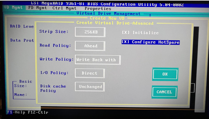
- After selecting the “Configure HotSpare” option, you will be asked to select which drives to use. You will select all 4 drives left that you didn’t select to be a part of the RAID volume and select “Ok” once done.

- Once you are done with configuring your RAID setup, you can save and power off the machine using “Ctrl + Alt + Del”.
- After the initialization screen and the HDD check screen, there will be a brief moment where you can press “ctrl + R” to boot to the RAID controller. This will appear shortly after the following boot screen.
- Install Ubuntu Linux 22.04 onto the boot drive.
- Make the root account possible to log into
- sudo passwd root
- set your password
- sudo passwd -u root
- su
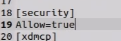
- gedit /etc/pam.d/gdm3/custom.conf
- Under “[Security]” add “Allow=True
- gedit /etc/pam.d/gdm-password
- Comment out “auth required pam_succeed_if.so user != root……..”

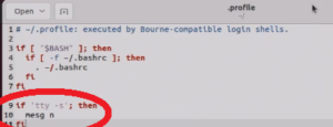
- gedit /root/.profile
- Delete the last row and add in the following lines of code
- if ‘tty -s’; then
- mesg n
- fi
- Restart the server. After the restart, you can choose “not listed” and log in as “root” with the password you set at the first command
- sudo passwd root
- Update and Upgrade your server
- apt-get update
- apt-get upgrade
- Install xfs tools
- apt-get install xfsprogs
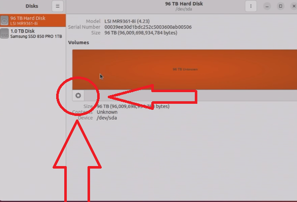
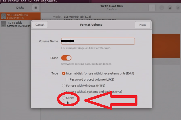
- Open the “Disks” app
- Select the 87TB RAID volume you are using as the iscsi storage
- Select the cog wheel on the left of the volume to make a partition
- Give the volume a name
- Select “other” and “next:
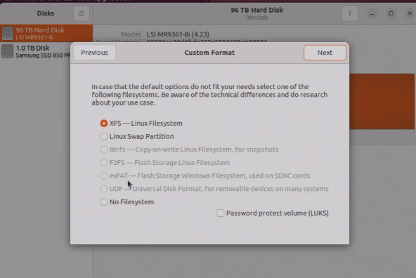
- Select “XFS” as the file system to format as and click next to start formatting.
- Make the partition persistent.
- Find the UUID of the partition
- blkid
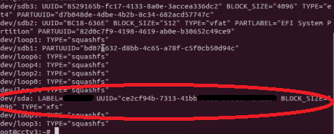
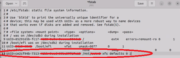
- Add the UUID to fstab
- gedit /etc/fstab
- Add “UUID=<your_uuid_here> /path/to/mount/location xfs defaults 0 2”
- mount -a
- gedit /etc/fstab
- Create ISCSI Share
- apt install tgt
- dd if=/dev/zero of=/path/to/mount/location/share.img bs=1M count=90000000
- THIS WILL TAKE A DAY TO COMPLETE
- tgtadm –lld iscsi –mode target –op new –tid 1 –targetname your_disk_name
- tgtadm –lld iscsi –mode logicalunit –op new –tid 1 –lun 1 -b /path/to/mount/location/share.img
- tgtadm –lld iscsi –mode target –op bind –tid 1 -I ALL
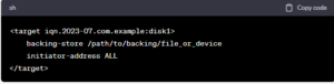
- gedit /etc/tgt/targets.conf
- Add this to the bottom of the file
- <target your_disk_name>
- backing-store /path/to/mount/location/share.img
- initiator-address ALL
- </target>
- Add this to the bottom of the file
- systemctl enable tgtchat
- Find the UUID of the partition
- Make the root account possible to log into
- Add ISCSI Share to Windows Server/Machine
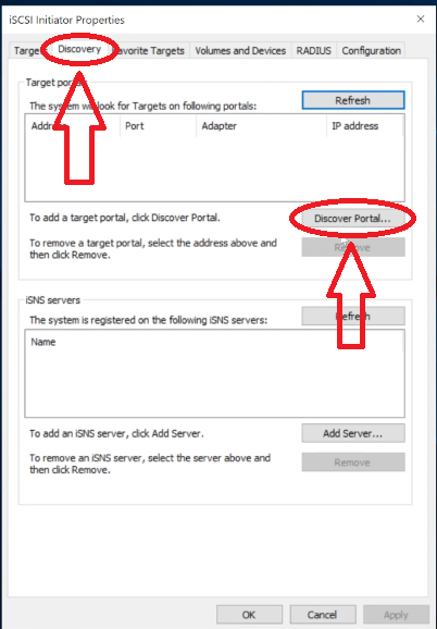
- Open “ISCSI Initiator” in windows search
- Go to “Discovery” and “Discover Portal”
- Enter the IP address of your Linux server in the IP address field and click “OK”
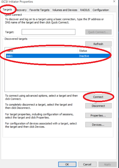
- Go back to the “Targets” page and see if your disk is listed. If so, click “Connect”.
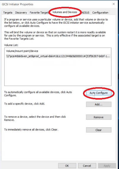
- Navigate to “Volumes and Devices” to set up auto-connecting. Just click “Auto-Configure”
- Make the drive in Disk Manager
- Open “Disk Manager”
- Right-click the offline drive and click “Online” to bring it online
- Right-click the empty volume and select “New Simple Volume”
- Go through the drive wizard. Give it a volume name, drive letter, etc.
- Create a script to Auto-Connect the drive when it falls offline
- Create a script called “connect.bat” anywhere on your server and edit it to have the following contents; it will need to be edited slightly to connect to your Linux server’s IP address.
- Powershell.exe -Command “& {Disconnect-IscsiTarget -cf:$false}”
@echo off
REM Connect to iSCSI Target Portal
echo Connecting to iSCSI Target Portal 192.168.1.xxx
iscsicli QAddTargetPortal 192.168.1.xxxREM List the available targets
echo List of Available Targets:
iscsicli ListTargetsREM Connect to a specific iSCSI target “your_share_name”
echo Connecting to target “your_share_name”
iscsicli QLoginTarget disk1echo Connection Successful!
rem pause
- Powershell.exe -Command “& {Disconnect-IscsiTarget -cf:$false}”
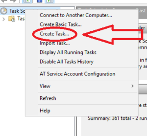
- Save the file and open “Task Scheduler”
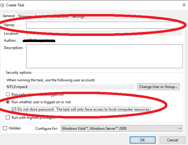
- Right-click “Task Scheduler (Local)” and Select “Create Task”
- Give the task a name, select “Run whether user is logged on or not” and check the “Do not store password” checkbox”
- Go to the “Triggers” tab and select “New”. Configure it the same as the image below (the start date will be different of course).
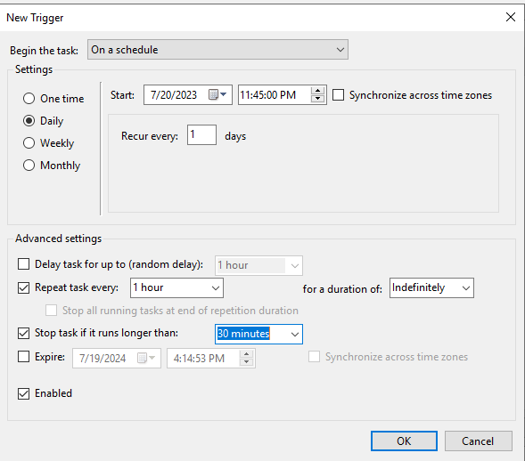
- Click “OK” when configured to your liking.
- Navigate to the “Actions” tab and click “New”
- Keep it on “Start a Program”
- Browse for the connect.bat file you made earlier
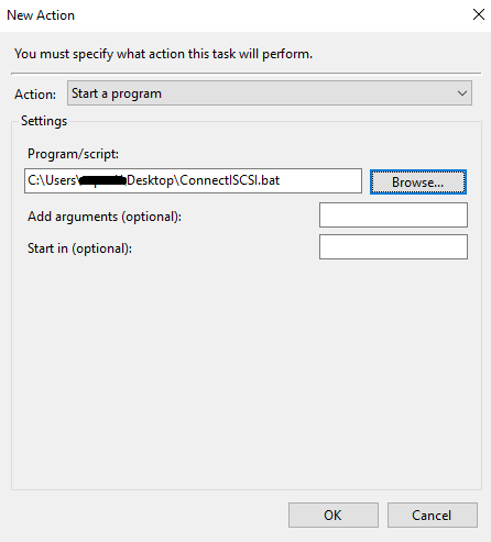
- Click “OK” to finish the task scheduling
- Create a script called “connect.bat” anywhere on your server and edit it to have the following contents; it will need to be edited slightly to connect to your Linux server’s IP address.
HP ProBook 650 G1 BIOS Programming
DISCLAIMER: I AM NOT RESPONSIBLE FOR ANY DAMAGE OR CORRUPTION ON YOUR DEVICE. THIS IS A RISKY PROCESS AND SHOULD ONLY BE DONE BY TRAINED PROFESSIONALS WITH PERMISSION FROM THE LAPTOP OWNER!
THIS SAME PROCESS CAN BE DONE WITH OTHER HP LAPTOPS AS WELL! The only difference is the model number of the chips.
This blog post is a tutorial for reprogramming the BIOS on an HP Probook 650 G1 laptop. This is meant to clear the BIOS administrator password which prevents any changes to be made to the system software. This is a risky process that can and has a high chance of bricking your laptop motherboard. Proceed with caution!
- Notes
- Remove the laptop battery for the whole process! The programmer provides power to the chip.
- HP is useless for helping with this. Reprogramming the chip is the only way of recovery for a locked/corrupted BIOS.
- The chip will most likely not fit on the chip due to the case getting in the way. I used a dremel to cut away at a piece of the case to make room for the chip. It doesn’t harm the laptop in any way or do external cosmetic damage.
- Getting the clip on the CMOS chip is VERY finicky. You will need to reseat it a few times before getting it right.
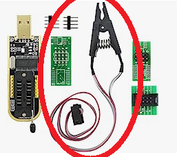
- Obtain a CH341 a BIOS programmer. Make sure the one you purchase has the clip with it (as shown below).
- Obtain the correct software capable of reading your chip (the model number of your chip is written on it).
- I use the software that came with the programmer called “ASProgrammer” with the version being 2.2.0.0. The specific model of the chip for most of these laptops is “25L12873F” which is fairly new hence the minimin version being 2.2.0.0.
- Unzip the file you downloaded, open the “Ch341a V2.2.0.0 > Drivers > CH341A” folder, and run the “Setup.exe” executable to install the drivers for the programmer.
- After installing the drivers, go to the “Ch341a V2.2.0.0” folder and run the “Ch341a V2.2.0.0.exe” executable to open the program. The software should automatically detect the programmer.
- Obtain the HP Unlocker tool to clear the password.
- This software is what you will use to actually clear the password after you read the password and can be found HERE.
- Unzip the tool and place it on your desktop.
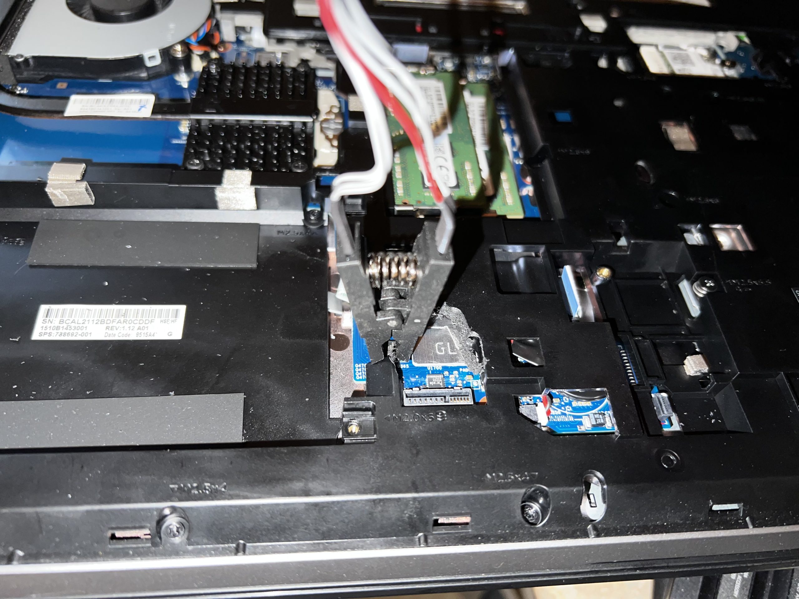
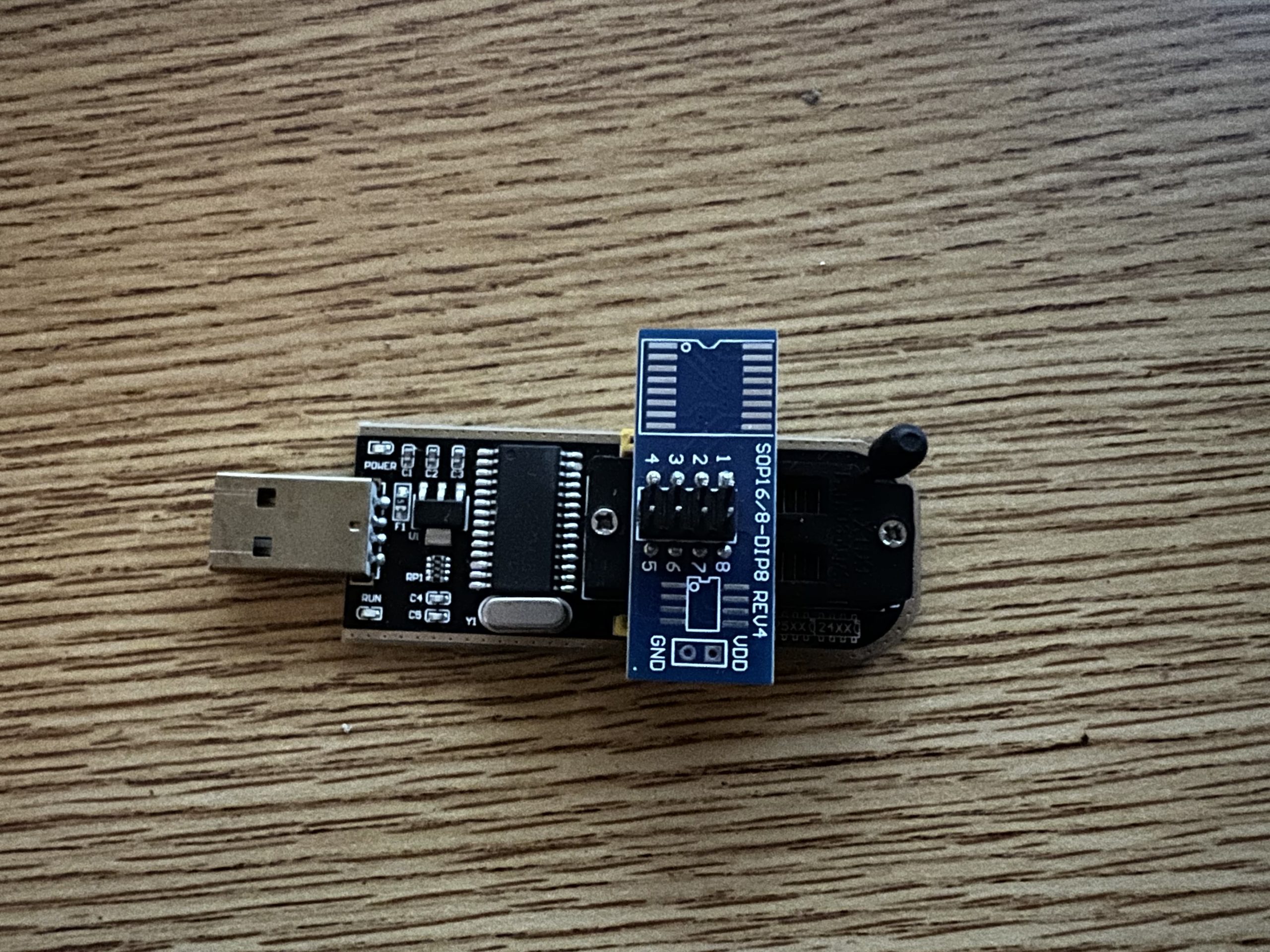
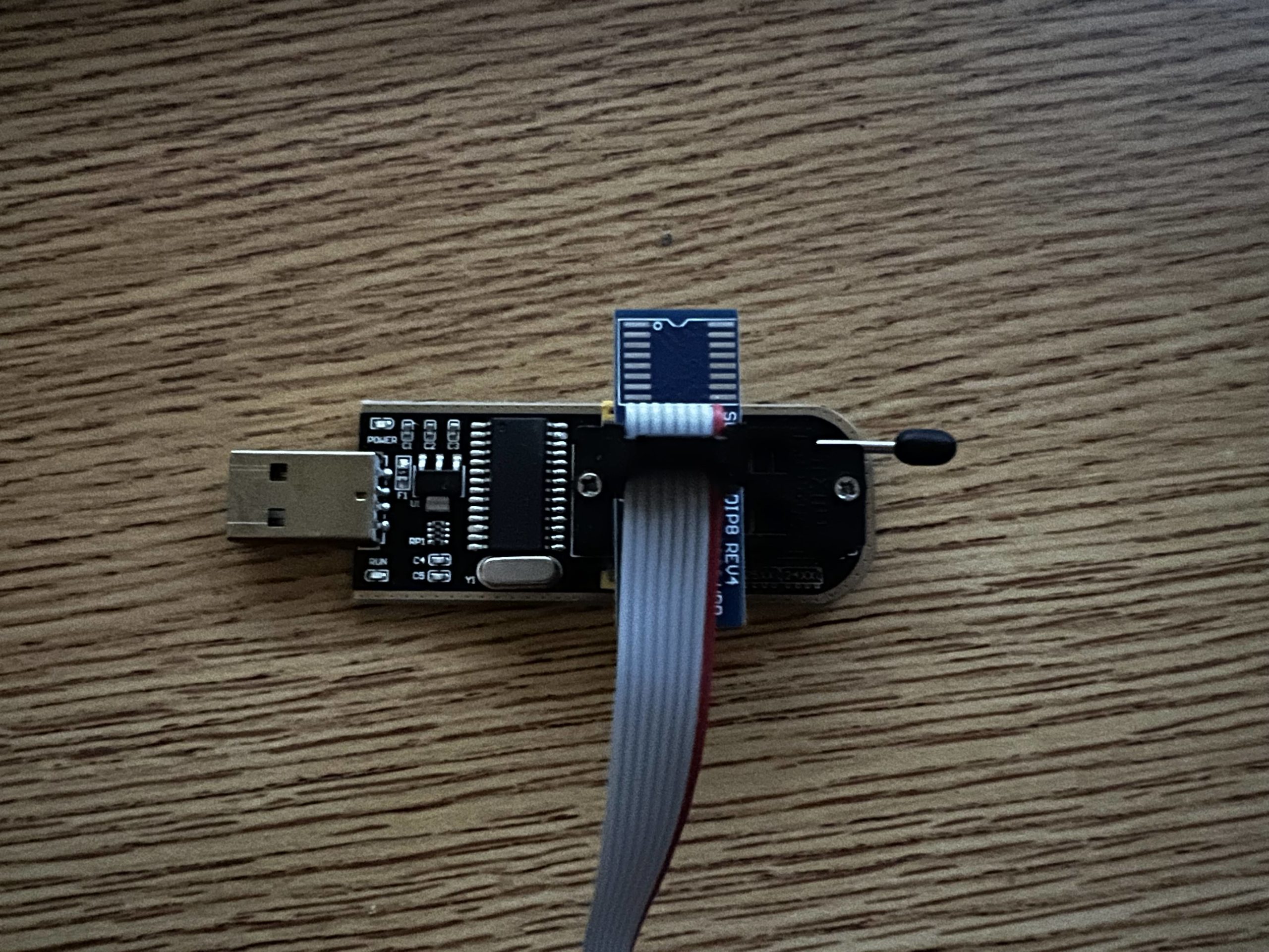
- Install the clip add-on to the BIOS programmer (as shown in the images below).
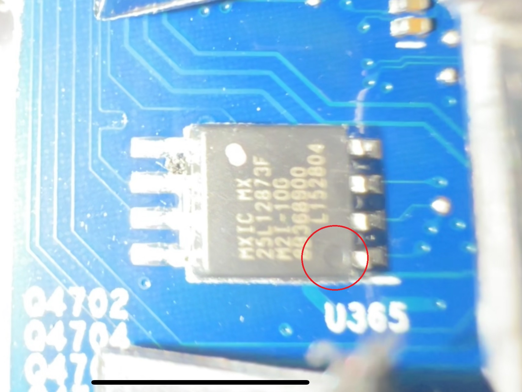
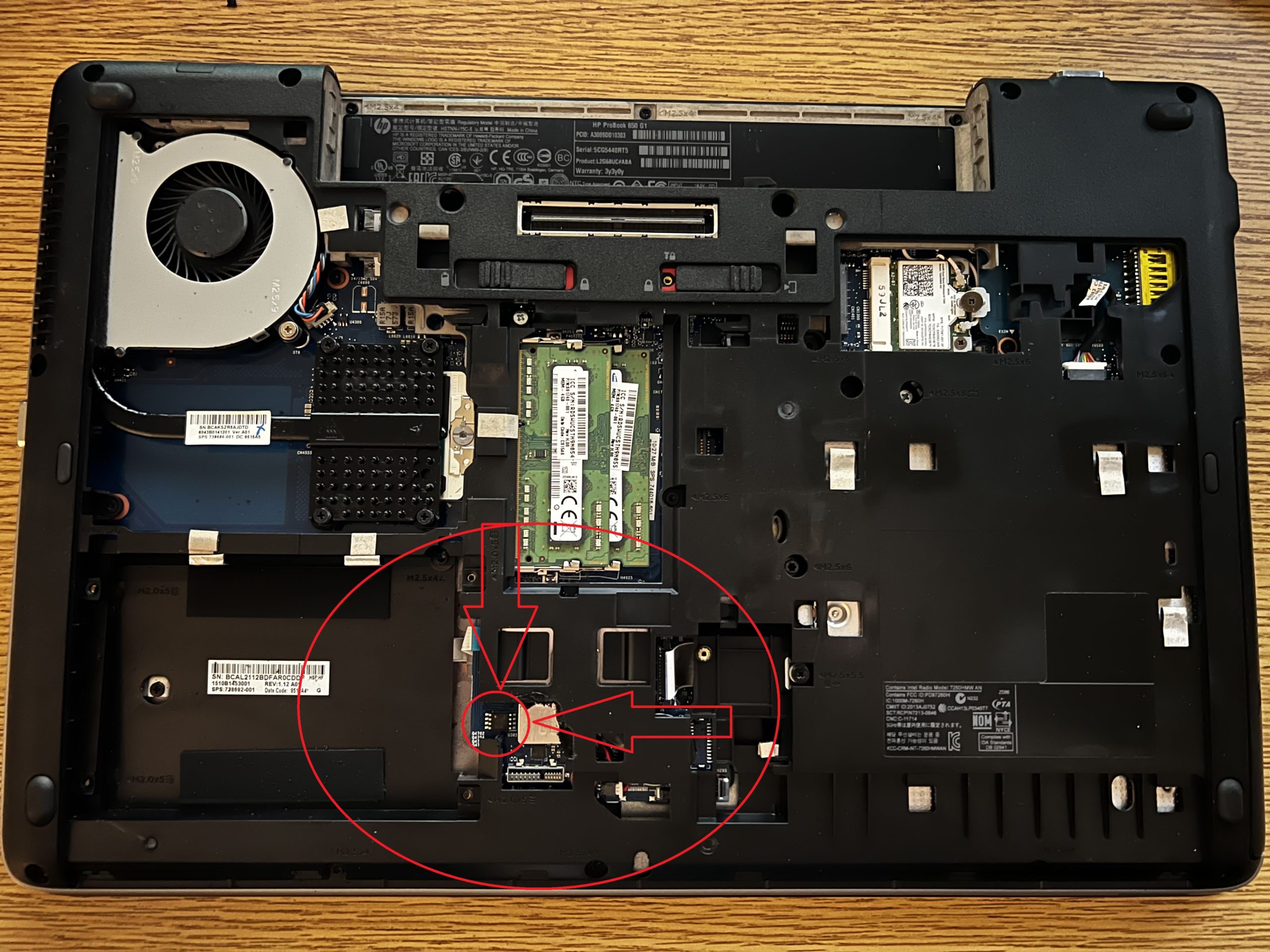
- Open the laptop and locate the BIOS chip (image below).
- Set The Clip on the CMOS Chip
- The corner of the clip that has a red wire needs to line up with the side of the chip with a small circular notch (as shown below).
- Program The Chip
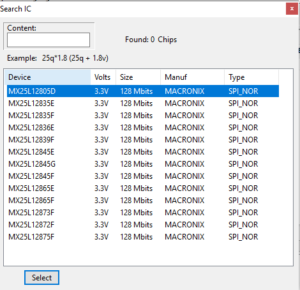
- Select Your Correct CMOS chip
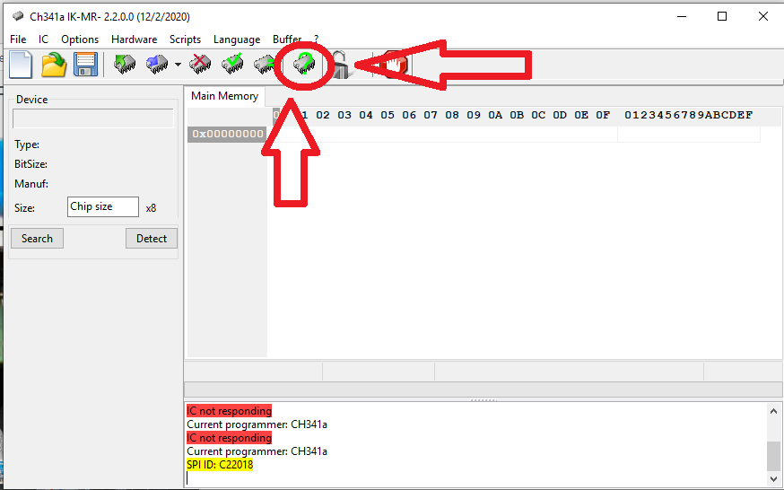
- Open/Run the CHA 341 software executable after plugging in the programmer and connecting it to the chip.
- Press the “Detect” button as shown below and select the chip you are programming.
- Read the chip
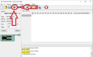
- After some time passes you will be left with a full output of hex code on the right side of the screen
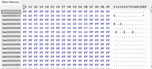
- Save the file to your desktop
- File > Save > Desktop.
- After saving, physically click and drag the file over the HP Unlocker program to create an “_unlocked” copy of the file.
- Load the _unlocked file into the ASProgrammer program.
- File > Open > yourfile_unlocked.bin
- Program the CMOS Chip
- After loading the unlocked file, you can hit the program button to program the CMOD chip.
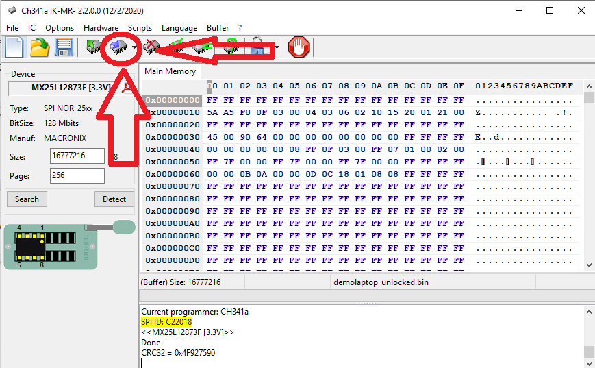
- After about 3-5 minutes, the software should show a success message at the bottom and you can remove the clip and enter a password-free bios!
- Select Your Correct CMOS chip
Aruba 2930M JL322A Switch Stack Replacement
This blog post is a step-by-step tutorial on replacing an Aruba 2930M JL322A 48 Port POE+ switch. This will cover the backup or configuration, pre-installation configuration (physical and logical), and physical installation of the switches into production.
- Assumptions
- You have unboxed all parts and have confirmed all are present.
- You have knowledge of how VLANs work and know how to properly connect the new stack to your core switch/router for testing purposes (tagging the correct VLANs on the right ports).
- Notes
- Do not power on or plug in the switches until you have the stacking cables connected!
- I use the traditional web GUI!
- I have had issues with downloading the config using the download button on the web interface.
- Parts rundown
- 4x Aruba 2930M JL322A Switches
- This includes power supplies and rackmount equipment.
- 2x Aruba JL083A SFP+ expansion card
- 1x Aruba SFP+ GBIC
- 4x Stacking Cables
- 4x Aruba 2930M JL322A Switches
- Getting the current config from the old switch stack
- Log into your switch stack’s IP address.
- Navigate to the “System” section and to the “Updates/Downloads” subsection.
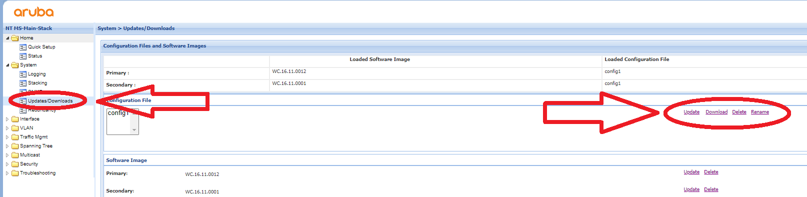
- Click the Download button to get the current configuration.
- Since you are doing this on a new switch stack, you want to delete the stacking config from the text file you downloaded. After deleting all of this from the file, you have a perfect config to paste into the new switch stack.
-
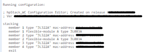
DELETE ALL OF THIS - You can alternatively go into the “Troubleshooting > Configuration Report” section to see the config in plain text on the web interface. You can then copy it into a text file and do the same thing if you have issues downloading it.
- Connecting Power Supply
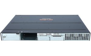
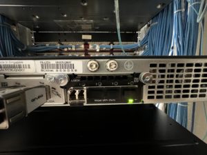
- Focus on the back of the switch, there will be two empty slots on the back. Remove the cover from one of the power supply slots (it doesn’t matter which) like the image shown below.
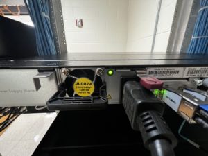
- Once the cover is removed, you can insert the power supply such as in the image below.
- Focus on the back of the switch, there will be two empty slots on the back. Remove the cover from one of the power supply slots (it doesn’t matter which) like the image shown below.
- Connecting Stacking Modules
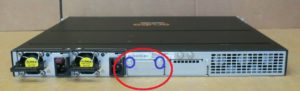
- Next to the power supply modules, there will be a port for the stacking module in the middle as shown in the image below. You need to remove the two screws circled in blue to take off the cover plate.
- Once the cover plate is removed, you can insert the stacking module as shown in the photo below
- Next to the power supply modules, there will be a port for the stacking module in the middle as shown in the image below. You need to remove the two screws circled in blue to take off the cover plate.
- Connecting SFP+ Expansion Card and Inserting GBIC
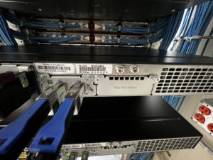
- On the far right, there is one last empty slot. This is for the SFP+ expansion slot. You need to remove the cover plate much like the stacking module cover plate. Once it is removed, you can slide the expansion card into the slot. It takes a little more force than expected; push until you hear a light click. You can then screw the card, remove one of the coverings, and insert the GBIC (it doesn’t matter which port you use, I decided to use port 1). See the photo below for reference.
- On the far right, there is one last empty slot. This is for the SFP+ expansion slot. You need to remove the cover plate much like the stacking module cover plate. Once it is removed, you can slide the expansion card into the slot. It takes a little more force than expected; push until you hear a light click. You can then screw the card, remove one of the coverings, and insert the GBIC (it doesn’t matter which port you use, I decided to use port 1). See the photo below for reference.
- Plugging in the stacking cables
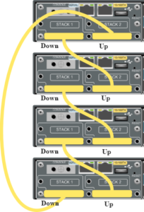
- Once you have all modules installed, you can connect the stacking cables. There is a diagram shown below (A different switch but the same outcome). Put simply, connect port 1 to port 2 on the switch under it and repeat.
- Once you have all modules installed, you can connect the stacking cables. There is a diagram shown below (A different switch but the same outcome). Put simply, connect port 1 to port 2 on the switch under it and repeat.
- Powering on and connecting to console
- Connect power to all switches. It will take 5 or so minutes to do the first-time boot process. You will know they are booted when there is a series of orange lights followed by a flash of green. After this is complete you can connect to the switch via the console port using a serial cable from another PC/Laptop.
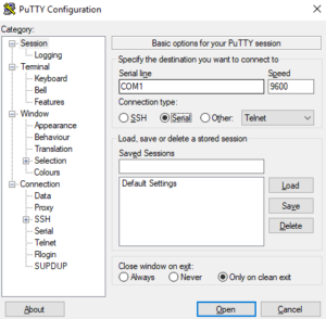
- Open PuTTY. You can then select the “Serial” option and connect to the switch.
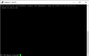
- Once here, you will log into the “manager” account and set a new password for first-time setup. You can then enter “show stack” to confirm all switches are connected and ready in the current stack.
- Connect power to all switches. It will take 5 or so minutes to do the first-time boot process. You will know they are booted when there is a series of orange lights followed by a flash of green. After this is complete you can connect to the switch via the console port using a serial cable from another PC/Laptop.
- Configuring switches
- At this point, you are ready to configure the switch stack. You will basically just paste the backup text file you made during the “Getting the current config from the old switch stack” step.
- If you want, you can change the configuration file to have different IP addresses for the VLANs. This will allow you to connect to the current stack and test connectivity before doing physical installation into the stack. For instance, you can change VLAN 1 to “192.168.5.3” instead of “10.66.5.2”. This will allow for testing without conflicting with the current switch stack.
- Method 1 – CMD Only
- Go into global configuration mode using the “conf t” command.
- Copy the config file and paste it into the console you are connected to by right-clicking. You can do small sections at a time to scan for errors as you go if you wish.
- WHEN YOU ARE DONE, DO A “write mem” COMMAND TO SAVE CHANGES.
- Method 2 – Web GUI
- Connect to the web interface (you can get your switch’s IP address using the “show ip” command).
- Log in and navigate to the “System > Updates/Downloads” section.
- Here you can download, upload, delete, and rename the config file. You will upload the file and update it.
- At this point, you are ready to configure the switch stack. You will basically just paste the backup text file you made during the “Getting the current config from the old switch stack” step.
- Test Switch Configuration
- After doing the config import, you can test various ports by plugging a PC into each port and seeing what IP address you get (this will test for connectivity and VLAN configuration). Ping outside addresses through the switch CMD, check the running config, check the stack status, etc).
- Physically Swap the Switch Stack
- This is pretty straightforward. Unplug everything from the old switches; do one switch at a time and keep track of which cords go to which port if you need to.
- Unscrew from the rack and replace it with the new one.
- Plug all ethernet cables into the new switch and eventually the stacking cables whenever all switches have been swapped out.
- Give power to the new production stack.
- Connect to the web GUI once the stack is up.
- Change the IP addresses of the switch if you need/want to and be done!
- Other Commands
- To change VLAN IDs on multiple ports
- conf t
- vlan 1
- Or whatever VLAN ID you want
- tagged 1/1-1/48
- This is to tag every port from port 1/1 to 1/48. This same command works for untagged as well.
- write mem
- To change the IP address of a VLAN interface
- conf t
- vlan 1
- Or whatever VLAN ID you want
- ip add 10.66.x.x 255.255.2xx.0
- write mem
- To remove an IP address from an interface
- conf t
- vlan 1
- Or whatever VLAN ID you want
- no ip add 10.66.x.x 255.255.2xx.0
- write mem
- To make an interface get an ip address from DHCP
- conf t
- vlan 1
- Or whatever VLAN ID you want
- ip addr dhcp-bootp
- write mem
- To disable ipv6 on all VLANS and OOBM
- conf t
- oobm
- no ipv6 enable
- no ipv6 address DHCP full
- exit
- vlan 1
- Or whatever VLAN ID you want
- no ipv6
- no ipv6 address DHCP full
- Rinse and repeat until you get through all VLANs.
- To show all modules on a switch (stacking modules and SFP+ modules
- show modules
- Updating the firmware of the switch
- Log into the web GUI
- Go to the “System” tab and the “Updates/Downloads” subtab.
- Under the “Software Image” section, click the “Update” button next to primary.
- Choose the switch file you downloaded from Arubas website
- Click the “Save” button and reboot the switch stack (they will all upgrade if they are stacked).
- Get a list of ACL’s
- show access-list
- Showing details for the switch (System Name, System Contact, System Location, MAC Age Time, Time Zone, and the System Serial Number).
- show system
- To change VLAN IDs on multiple ports