This blog post is a step-by-step tutorial on replacing an Aruba 2930M JL322A 48 Port POE+ switch. This will cover the backup or configuration, pre-installation configuration (physical and logical), and physical installation of the switches into production.
- Assumptions
- You have unboxed all parts and have confirmed all are present.
- You have knowledge of how VLANs work and know how to properly connect the new stack to your core switch/router for testing purposes (tagging the correct VLANs on the right ports).
- Notes
- Do not power on or plug in the switches until you have the stacking cables connected!
- I use the traditional web GUI!
- I have had issues with downloading the config using the download button on the web interface.
- Parts rundown
- 4x Aruba 2930M JL322A Switches
- This includes power supplies and rackmount equipment.
- 2x Aruba JL083A SFP+ expansion card
- 1x Aruba SFP+ GBIC
- 4x Stacking Cables
- 4x Aruba 2930M JL322A Switches
- Getting the current config from the old switch stack
- Log into your switch stack’s IP address.
- Navigate to the “System” section and to the “Updates/Downloads” subsection.
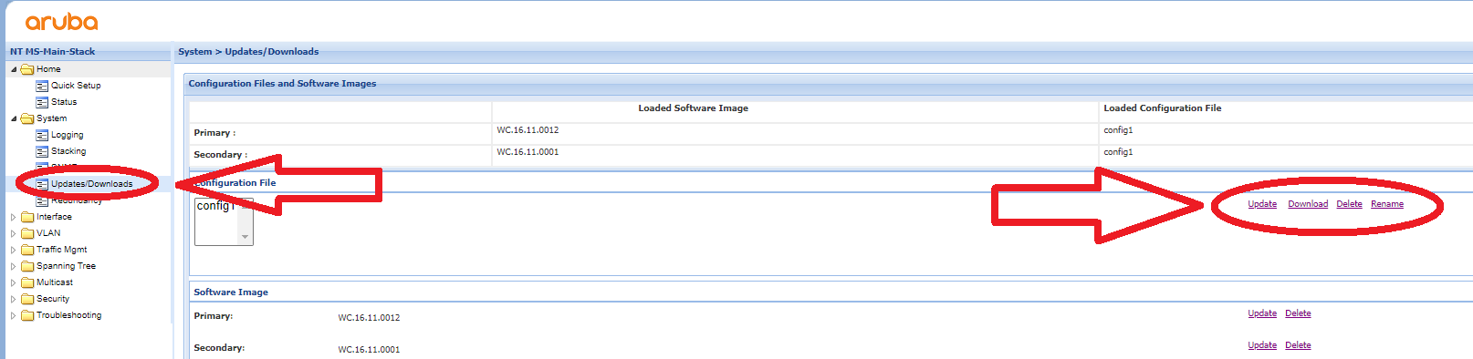
- Click the Download button to get the current configuration.
- Since you are doing this on a new switch stack, you want to delete the stacking config from the text file you downloaded. After deleting all of this from the file, you have a perfect config to paste into the new switch stack.
-
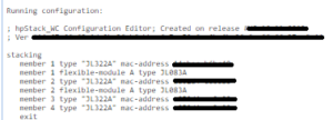
DELETE ALL OF THIS - You can alternatively go into the “Troubleshooting > Configuration Report” section to see the config in plain text on the web interface. You can then copy it into a text file and do the same thing if you have issues downloading it.
- Connecting Power Supply
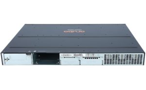
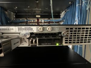
- Focus on the back of the switch, there will be two empty slots on the back. Remove the cover from one of the power supply slots (it doesn’t matter which) like the image shown below.
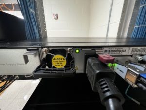
- Once the cover is removed, you can insert the power supply such as in the image below.
- Focus on the back of the switch, there will be two empty slots on the back. Remove the cover from one of the power supply slots (it doesn’t matter which) like the image shown below.
- Connecting Stacking Modules
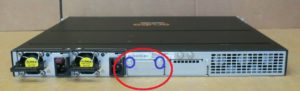
- Next to the power supply modules, there will be a port for the stacking module in the middle as shown in the image below. You need to remove the two screws circled in blue to take off the cover plate.
- Once the cover plate is removed, you can insert the stacking module as shown in the photo below
- Next to the power supply modules, there will be a port for the stacking module in the middle as shown in the image below. You need to remove the two screws circled in blue to take off the cover plate.
- Connecting SFP+ Expansion Card and Inserting GBIC
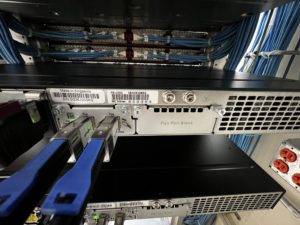
- On the far right, there is one last empty slot. This is for the SFP+ expansion slot. You need to remove the cover plate much like the stacking module cover plate. Once it is removed, you can slide the expansion card into the slot. It takes a little more force than expected; push until you hear a light click. You can then screw the card, remove one of the coverings, and insert the GBIC (it doesn’t matter which port you use, I decided to use port 1). See the photo below for reference.
- On the far right, there is one last empty slot. This is for the SFP+ expansion slot. You need to remove the cover plate much like the stacking module cover plate. Once it is removed, you can slide the expansion card into the slot. It takes a little more force than expected; push until you hear a light click. You can then screw the card, remove one of the coverings, and insert the GBIC (it doesn’t matter which port you use, I decided to use port 1). See the photo below for reference.
- Plugging in the stacking cables
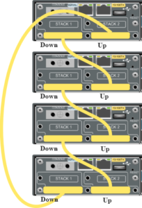
- Once you have all modules installed, you can connect the stacking cables. There is a diagram shown below (A different switch but the same outcome). Put simply, connect port 1 to port 2 on the switch under it and repeat.
- Once you have all modules installed, you can connect the stacking cables. There is a diagram shown below (A different switch but the same outcome). Put simply, connect port 1 to port 2 on the switch under it and repeat.
- Powering on and connecting to console
- Connect power to all switches. It will take 5 or so minutes to do the first-time boot process. You will know they are booted when there is a series of orange lights followed by a flash of green. After this is complete you can connect to the switch via the console port using a serial cable from another PC/Laptop.
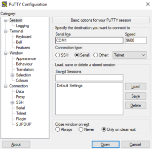
- Open PuTTY. You can then select the “Serial” option and connect to the switch.
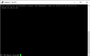
- Once here, you will log into the “manager” account and set a new password for first-time setup. You can then enter “show stack” to confirm all switches are connected and ready in the current stack.
- Connect power to all switches. It will take 5 or so minutes to do the first-time boot process. You will know they are booted when there is a series of orange lights followed by a flash of green. After this is complete you can connect to the switch via the console port using a serial cable from another PC/Laptop.
- Configuring switches
- At this point, you are ready to configure the switch stack. You will basically just paste the backup text file you made during the “Getting the current config from the old switch stack” step.
- If you want, you can change the configuration file to have different IP addresses for the VLANs. This will allow you to connect to the current stack and test connectivity before doing physical installation into the stack. For instance, you can change VLAN 1 to “192.168.5.3” instead of “10.66.5.2”. This will allow for testing without conflicting with the current switch stack.
- Method 1 – CMD Only
- Go into global configuration mode using the “conf t” command.
- Copy the config file and paste it into the console you are connected to by right-clicking. You can do small sections at a time to scan for errors as you go if you wish.
- WHEN YOU ARE DONE, DO A “write mem” COMMAND TO SAVE CHANGES.
- Method 2 – Web GUI
- Connect to the web interface (you can get your switch’s IP address using the “show ip” command).
- Log in and navigate to the “System > Updates/Downloads” section.
- Here you can download, upload, delete, and rename the config file. You will upload the file and update it.
- At this point, you are ready to configure the switch stack. You will basically just paste the backup text file you made during the “Getting the current config from the old switch stack” step.
- Test Switch Configuration
- After doing the config import, you can test various ports by plugging a PC into each port and seeing what IP address you get (this will test for connectivity and VLAN configuration). Ping outside addresses through the switch CMD, check the running config, check the stack status, etc).
- Physically Swap the Switch Stack
- This is pretty straightforward. Unplug everything from the old switches; do one switch at a time and keep track of which cords go to which port if you need to.
- Unscrew from the rack and replace it with the new one.
- Plug all ethernet cables into the new switch and eventually the stacking cables whenever all switches have been swapped out.
- Give power to the new production stack.
- Connect to the web GUI once the stack is up.
- Change the IP addresses of the switch if you need/want to and be done!
- Other Commands
- To change VLAN IDs on multiple ports
- conf t
- vlan 1
- Or whatever VLAN ID you want
- tagged 1/1-1/48
- This is to tag every port from port 1/1 to 1/48. This same command works for untagged as well.
- write mem
- To change the IP address of a VLAN interface
- conf t
- vlan 1
- Or whatever VLAN ID you want
- ip add 10.66.x.x 255.255.2xx.0
- write mem
- To remove an IP address from an interface
- conf t
- vlan 1
- Or whatever VLAN ID you want
- no ip add 10.66.x.x 255.255.2xx.0
- write mem
- To make an interface get an ip address from DHCP
- conf t
- vlan 1
- Or whatever VLAN ID you want
- ip addr dhcp-bootp
- write mem
- To disable ipv6 on all VLANS and OOBM
- conf t
- oobm
- no ipv6 enable
- no ipv6 address DHCP full
- exit
- vlan 1
- Or whatever VLAN ID you want
- no ipv6
- no ipv6 address DHCP full
- Rinse and repeat until you get through all VLANs.
- To show all modules on a switch (stacking modules and SFP+ modules
- show modules
- Updating the firmware of the switch
- Log into the web GUI
- Go to the “System” tab and the “Updates/Downloads” subtab.
- Under the “Software Image” section, click the “Update” button next to primary.
- Choose the switch file you downloaded from Arubas website
- Click the “Save” button and reboot the switch stack (they will all upgrade if they are stacked).
- Get a list of ACL’s
- show access-list
- Showing details for the switch (System Name, System Contact, System Location, MAC Age Time, Time Zone, and the System Serial Number).
- show system
- To change VLAN IDs on multiple ports