This is a blog post focusing on creating an ISCSI share on Ubuntu Linux on an Icebreaker 4936 Server. This will act as a mass storage ISCSI store for a Windows file and video server. I will describe the process of creating the ISCSI server, connecting it to Windows, and ensuring a stable connection through a series of scripts on Windows.
OS: Ubuntu Linux 22.04
- Assumptions
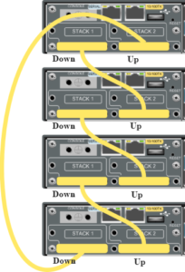
- You have already completed the “Quick Start Guide” by connecting the raid controller components to each other inside of the case.
- The hard drives have already been slotted into the hot swap bays.
- The system is able to be powered on and is capable of entering BIOS.
- You have created an Ubuntu Linux bootable USB drive.
- You know how to install Windows 10/Windows Server and Ubuntu 22.04.
- Connect a keyboard, mouse, and monitor to the server.
- Create a bootable disk to Windows 10/Windows Server 2016 or newer to do drive testing.
- Download the Seatools drive testing software.
- Download the StorCLI command line tools.
- Open the command prompt and navigate to the directory where the storclt.exe executable is.
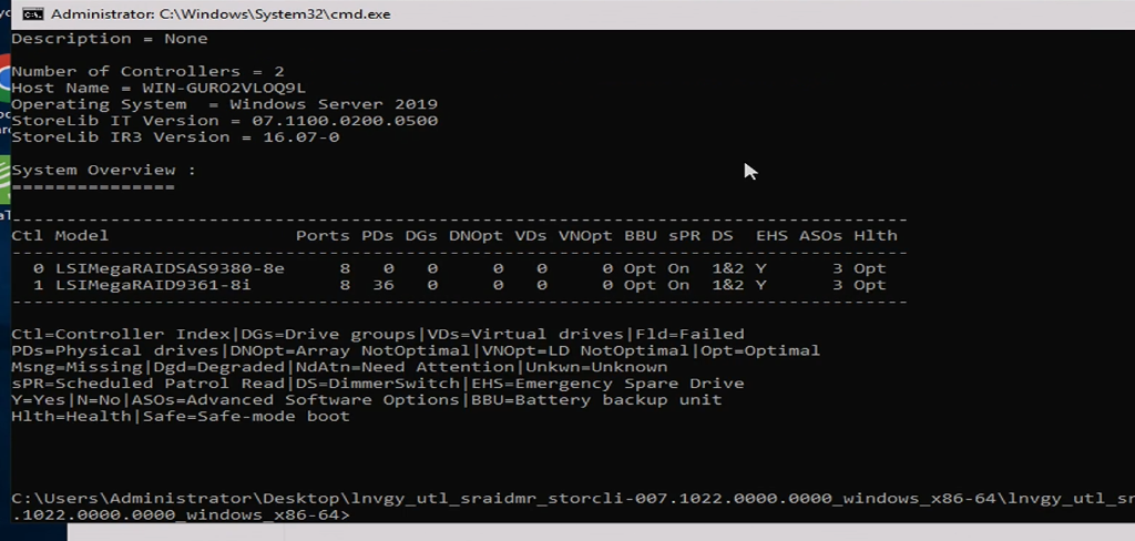
- List all RAID controllers
- storcli show
- There should be a list of two raid controllers, one with no PDs, and one with 36.
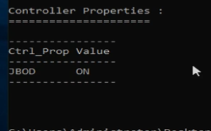
- Put the RAID controller in JBOD mode.
- storcli /c1 set jbod=on
- Put disks in JBOD mode
- storcli /c1/eall/sall set jbod
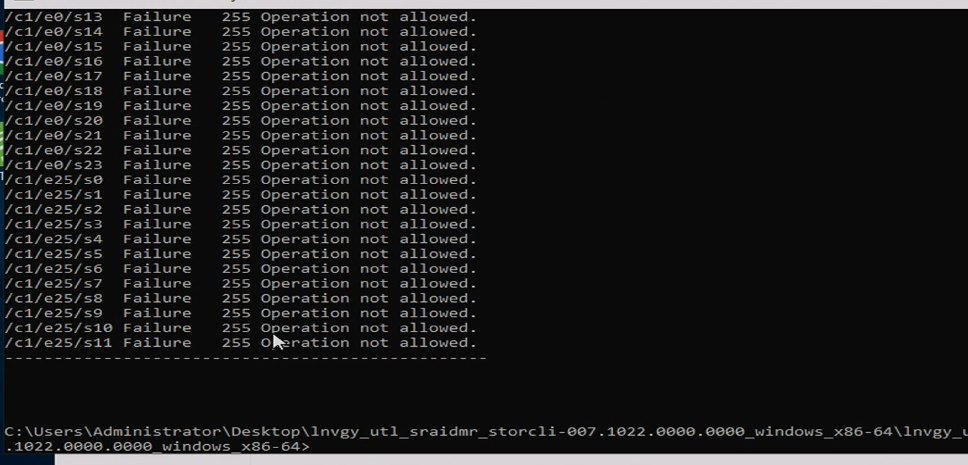
- It WILL say that each disk failed to go to jbod mode. This is not true, the operation worked.
- Restart the server
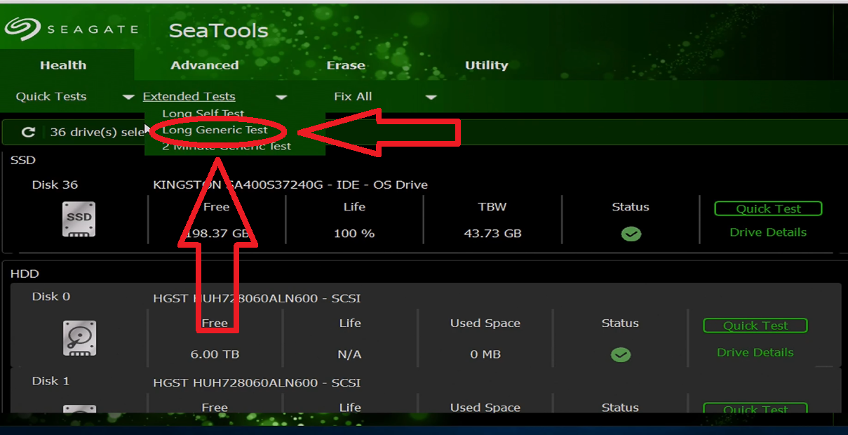
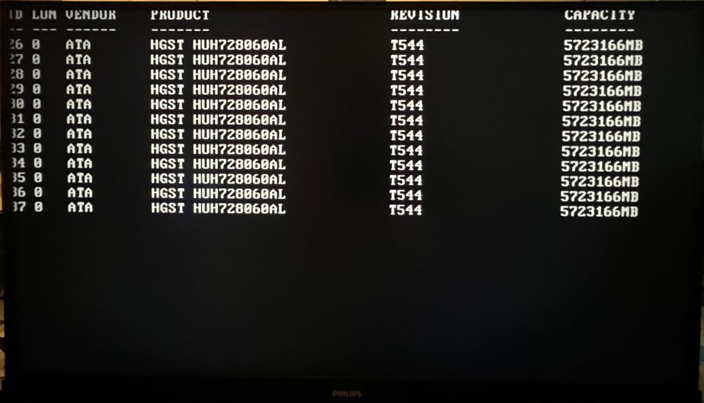
- Open the Seatools software. There should be all 36 drives + the OS drive.
- Select every drive you want to test. This can be done by doing “Ctrl + Left Click” to select multiple drives at once.
- Perform a Long Generic Test by clicking the button as shown in the photo below.
- After multiple days pass, you should be left with an outcome of what drives are good/bad. Replace the bad ones if necessary.
- Restart on the machine to boot to the RAID controller.
- After the initialization screen and the HDD check screen, there will be a brief moment where you can press “ctrl + R” to boot to the RAID controller. This will appear shortly after the following boot screen.
- Once on the controller interface, you can select your RAID configuration. This includes the RAID level, which drives you to want to use, setting up hot failover, and how many physical drives you want for each logical drive. In my case, I used RAID 10 with 18 drive logical drives (18 striped, 18 mirrored).
- The RAID card included with this server supports RAID 0, 1, 5, 6, 10, and 50. For more information and visualizations of the different raid levels, visit the link HERE.
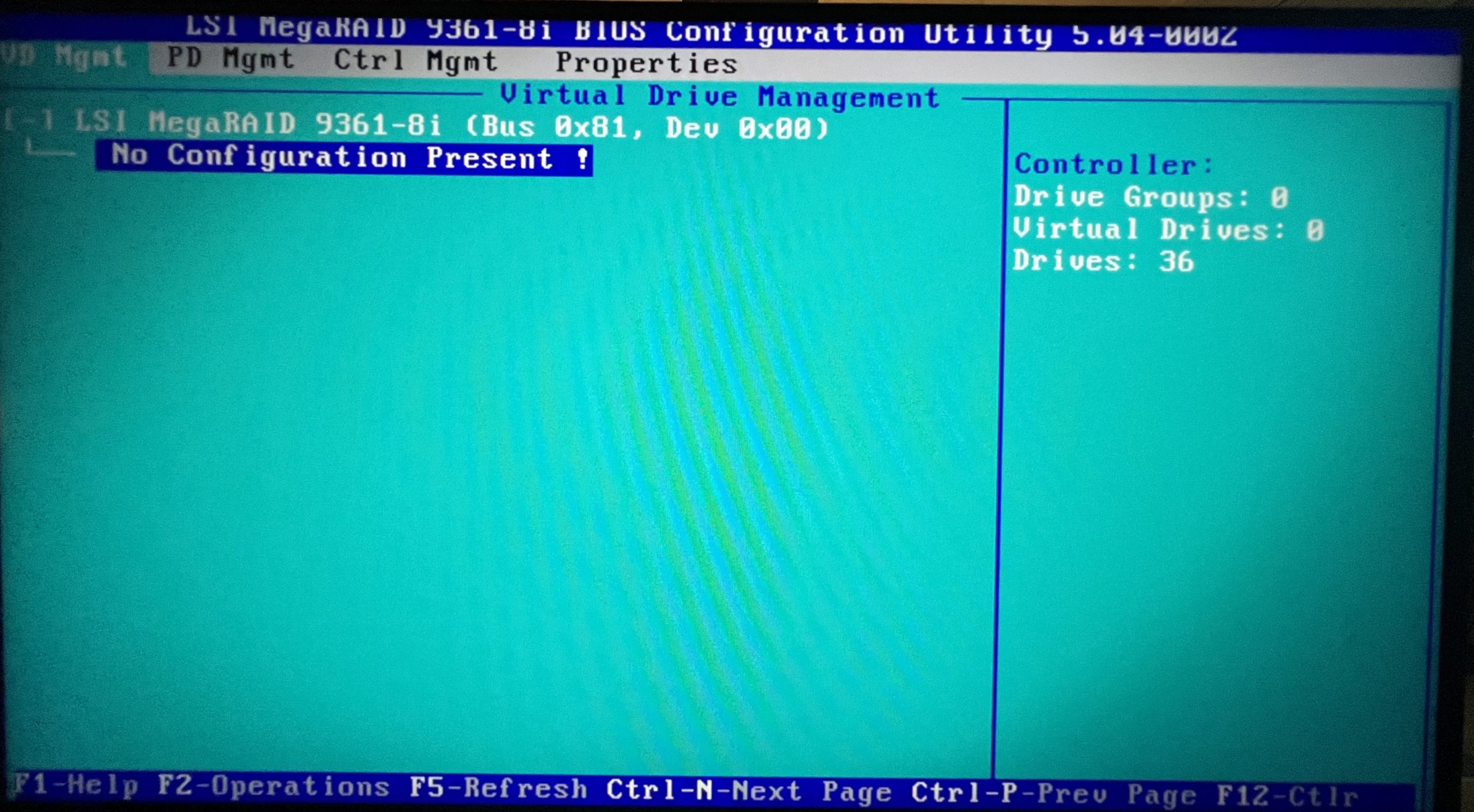
- The main screen of the RAID controller should look like the photo below.
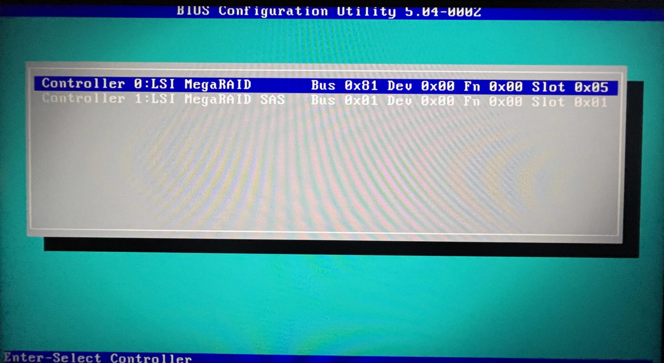
- You then need to select the “Controller 1: LSI MegaRAID SAS” card to configure the drives.
- You will be greeted with a mostly-empty screen that looks like the following.
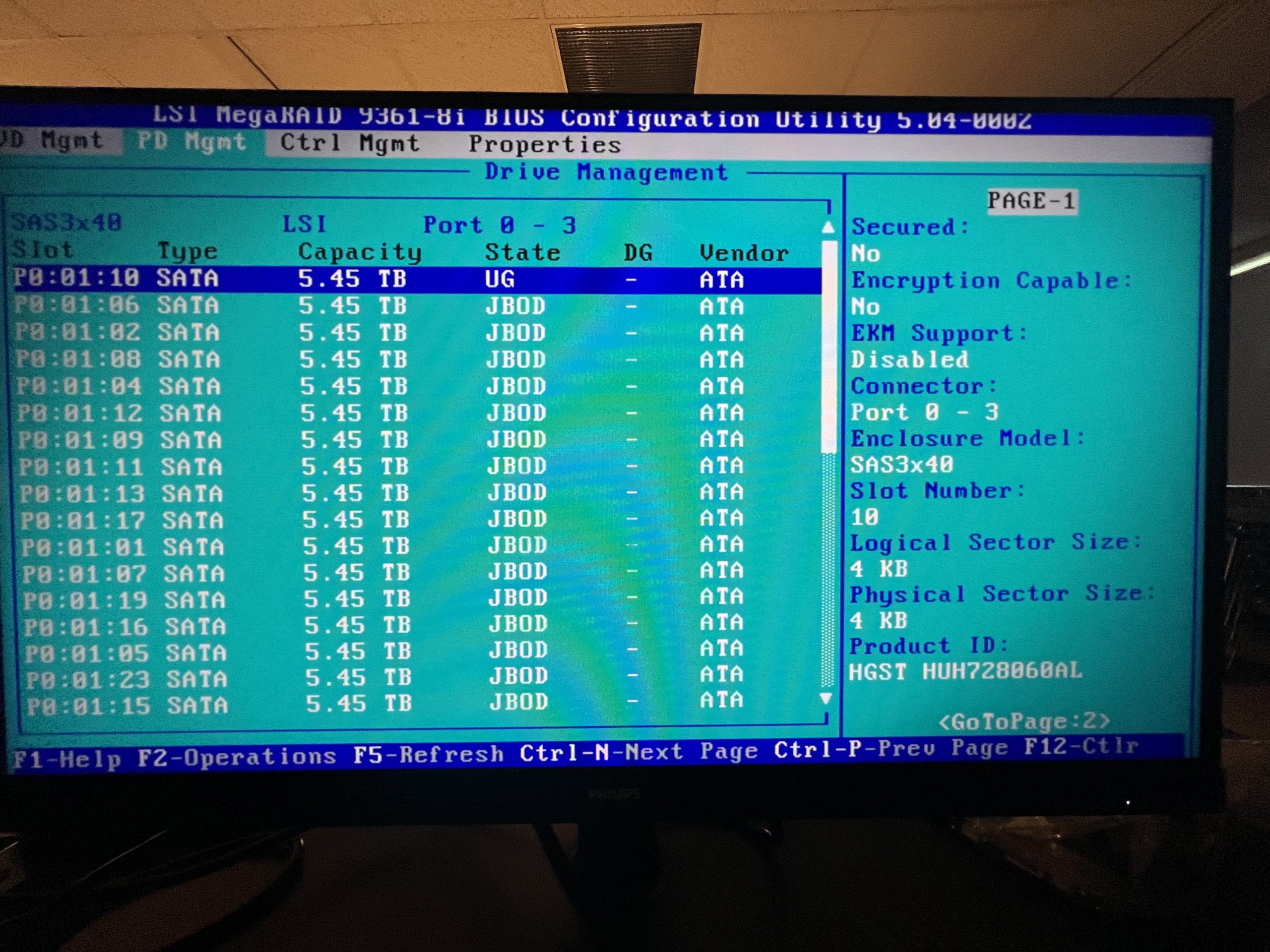
- Press “Crtl + N” to go to the “PD Mgmt” page where you will be a list of disks in “JBOD” mode.
- Select each disk one at a time
- Press “F2”
- Select “Make Unconfigured Good”
- Say “Yes” to the warning about losing data.
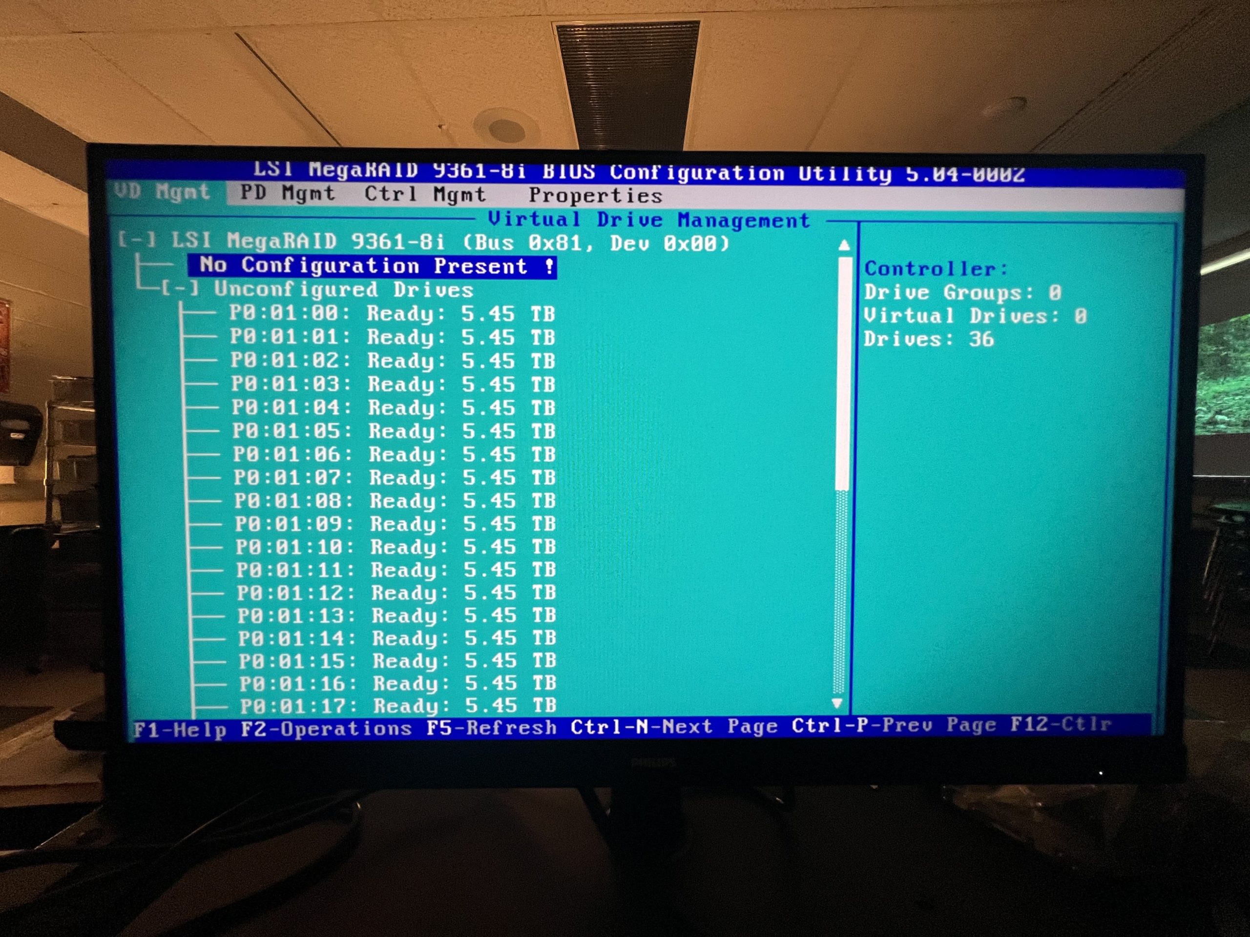
- Repeat until all disks are in “UG” mode like the one shown below.
- Press “Ctrl + P” to go back to the “VD Mgmt” page.
- There should be a large list of unconfigured drives that are “Ready”.
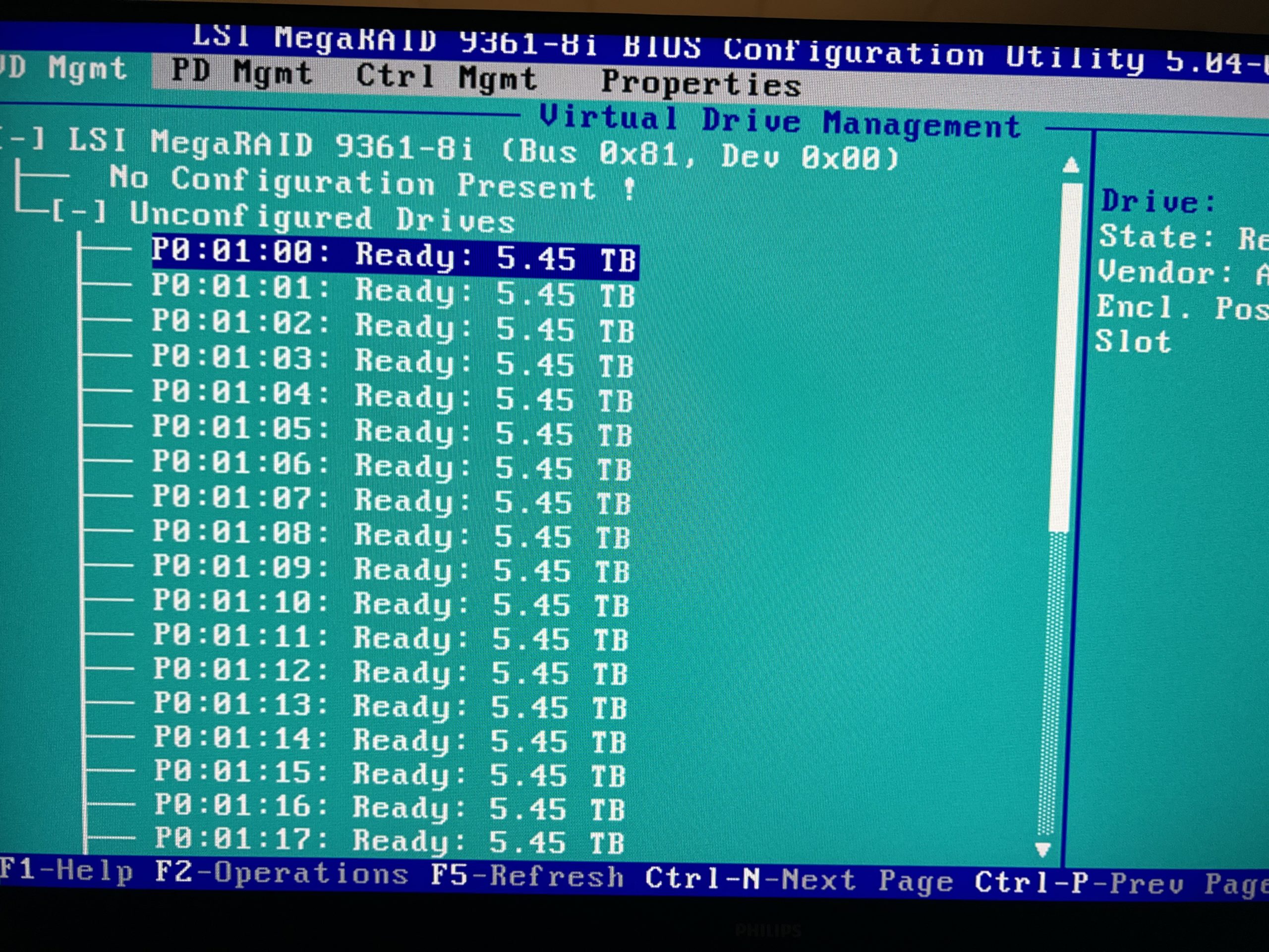
- Scroll up to where it says “No Configuration Present!”
- Next, press “F2” to enter the Raid Setup menu.
- Here, select “Raid-10” for the RAID Level.
- “PD per Span” should be 18.
- Next, go through and press enter to select 32 total drives, leaving 4 to be HotSpares.
- The size should be around 87TB and you can name the drive what you wish.
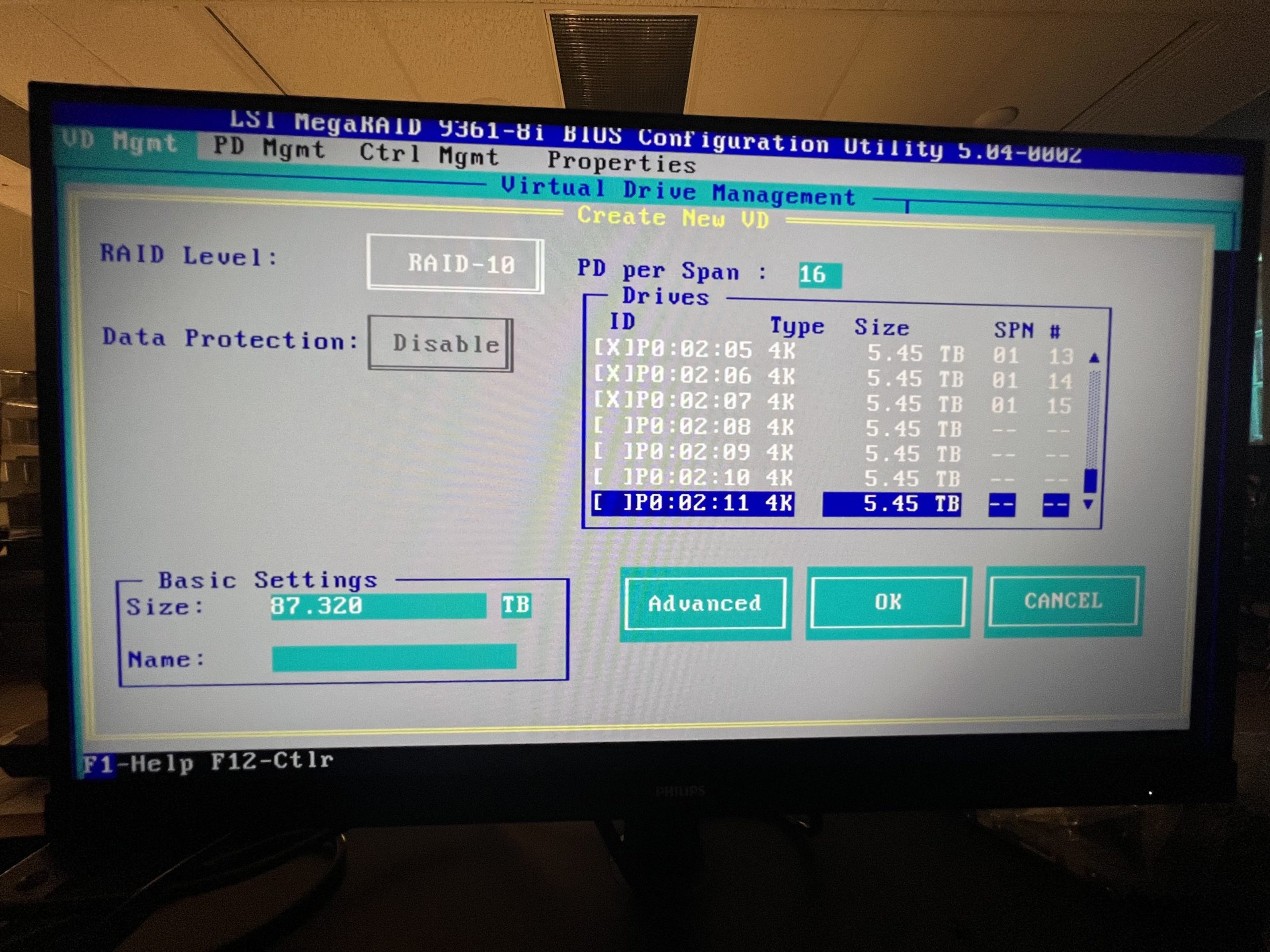
- Next, enter the “Advanced” options
- Here, you need to check “Initialize” and “Configure HotSpare”
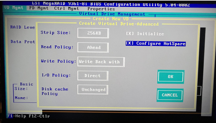
- After selecting the “Configure HotSpare” option, you will be asked to select which drives to use. You will select all 4 drives left that you didn’t select to be a part of the RAID volume and select “Ok” once done.

- Once you are done with configuring your RAID setup, you can save and power off the machine using “Ctrl + Alt + Del”.
- After the initialization screen and the HDD check screen, there will be a brief moment where you can press “ctrl + R” to boot to the RAID controller. This will appear shortly after the following boot screen.
- Install Ubuntu Linux 22.04 onto the boot drive.
- Make the root account possible to log into
- sudo passwd root
- set your password
- sudo passwd -u root
- su
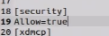
- gedit /etc/pam.d/gdm3/custom.conf
- Under “[Security]” add “Allow=True
- gedit /etc/pam.d/gdm-password
- Comment out “auth required pam_succeed_if.so user != root……..”

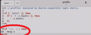
- gedit /root/.profile
- Delete the last row and add in the following lines of code
- if ‘tty -s’; then
- mesg n
- fi
- Restart the server. After the restart, you can choose “not listed” and log in as “root” with the password you set at the first command
- sudo passwd root
- Update and Upgrade your server
- apt-get update
- apt-get upgrade
- Install xfs tools
- apt-get install xfsprogs
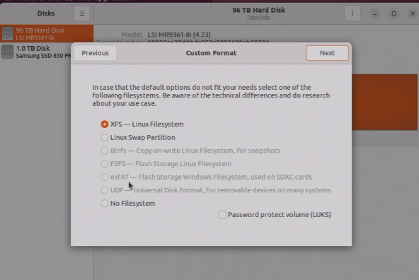
- Open the “Disks” app
- Select the 87TB RAID volume you are using as the iscsi storage
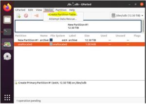
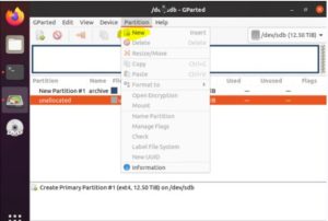
- Select the cog wheel on the left of the volume to make a partition
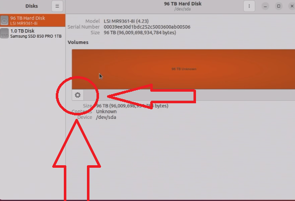
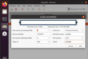
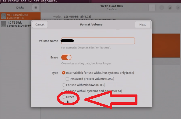
- Give the volume a name
- Select “other” and “next:
- Select “XFS” as the file system to format as and click next to start formatting.
- Make the partition persistent.
- Find the UUID of the partition
- blkid
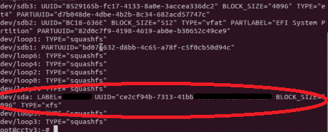
- Add the UUID to fstab
- gedit /etc/fstab
- Add “UUID=<your_uuid_here> /path/to/mount/location xfs defaults 0 2”
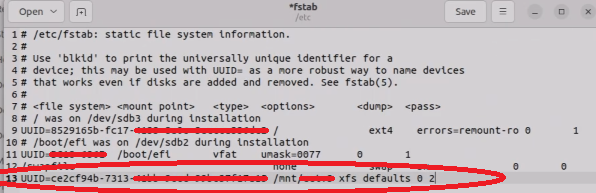
- mount -a
- gedit /etc/fstab
- Create ISCSI Share
- apt install tgt
- dd if=/dev/zero of=/path/to/mount/location/share.img bs=1M count=90000000
- THIS WILL TAKE A DAY TO COMPLETE
- tgtadm –lld iscsi –mode target –op new –tid 1 –targetname your_disk_name
- tgtadm –lld iscsi –mode logicalunit –op new –tid 1 –lun 1 -b /path/to/mount/location/share.img
- tgtadm –lld iscsi –mode target –op bind –tid 1 -I ALL
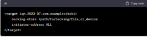
- gedit /etc/tgt/targets.conf
- Add this to the bottom of the file
- <target your_disk_name>
- backing-store /path/to/mount/location/share.img
- initiator-address ALL
- </target>
- Add this to the bottom of the file
- systemctl enable tgtchat
- Find the UUID of the partition
- Make the root account possible to log into
- Add ISCSI Share to Windows Server/Machine
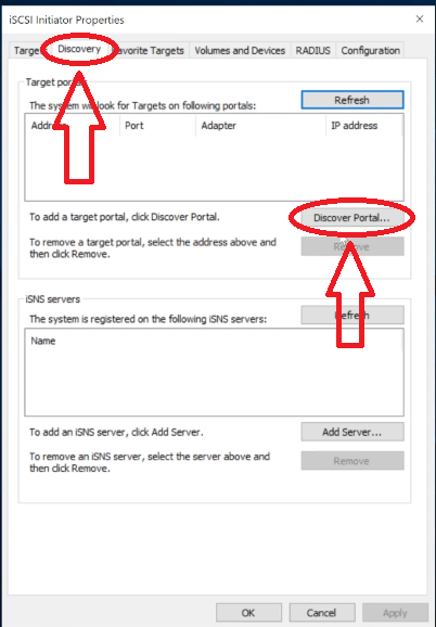
- Open “ISCSI Initiator” in windows search
- Go to “Discovery” and “Discover Portal”
- Enter the IP address of your Linux server in the IP address field and click “OK”
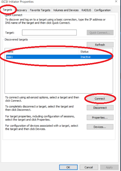
- Go back to the “Targets” page and see if your disk is listed. If so, click “Connect”.
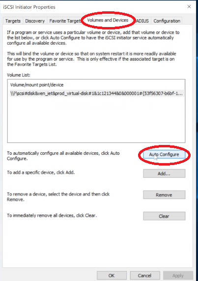
- Navigate to “Volumes and Devices” to set up auto-connecting. Just click “Auto-Configure”
- Make the drive in Disk Manager
- Open “Disk Manager”
- Right-click the offline drive and click “Online” to bring it online
- Right-click the empty volume and select “New Simple Volume”
- Go through the drive wizard. Give it a volume name, drive letter, etc.
- Create a script to Auto-Connect the drive when it falls offline
- Create a script called “connect.bat” anywhere on your server and edit it to have the following contents; it will need to be edited slightly to connect to your Linux server’s IP address.
- Powershell.exe -Command “& {Disconnect-IscsiTarget -cf:$false}”
@echo off
REM Connect to iSCSI Target Portal
echo Connecting to iSCSI Target Portal 192.168.1.xxx
iscsicli QAddTargetPortal 192.168.1.xxxREM List the available targets
echo List of Available Targets:
iscsicli ListTargetsREM Connect to a specific iSCSI target “your_share_name”
echo Connecting to target “your_share_name”
iscsicli QLoginTarget disk1echo Connection Successful!
rem pause
- Powershell.exe -Command “& {Disconnect-IscsiTarget -cf:$false}”
- Save the file and open “Task Scheduler”
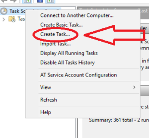
- Right-click “Task Scheduler (Local)” and Select “Create Task”
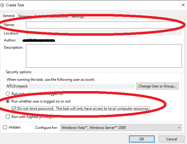
- Give the task a name, select “Run whether user is logged on or not” and check the “Do not store password” checkbox”
- Go to the “Triggers” tab and select “New”. Configure it the same as the image below (the start date will be different of course).
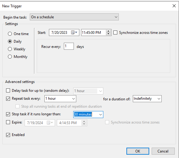
- Click “OK” when configured to your liking.
- Navigate to the “Actions” tab and click “New”
- Keep it on “Start a Program”
- Browse for the connect.bat file you made earlier
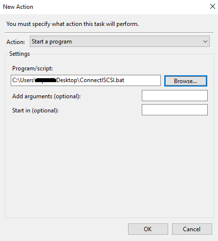
- Click “OK” to finish the task scheduling
- Create a script called “connect.bat” anywhere on your server and edit it to have the following contents; it will need to be edited slightly to connect to your Linux server’s IP address.
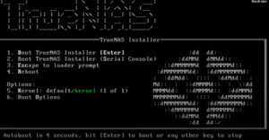 After the initial initialize page, you can press “1” to select the “Install/Upgrade” option
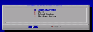 You can then say yes to your data being wiped, enter a password, and to “Boot Via BIOS” you can choose UEFI if you want, I just chose BIOS since it is compatible with our legacy devices.
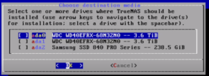
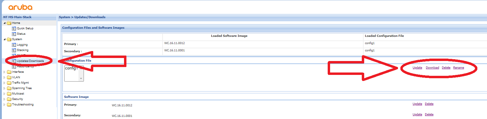
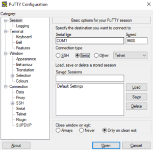
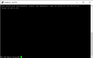
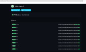
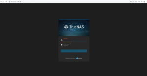 Enter the Web GUI